Message Boards Message Boards

1
|
27372 Views
|
8 Replies
|
1 Total Likes
View groups...
Share
Share this post:

Reading potentiometer values through your Arduino with your Raspberry Pi

Posted 11 years ago
This post shows how to read an analog value from an Arduino Uno over a serial connection using the Wolfram Language.

To recreate this experiment you will need the following hardware:


As a first step upload the following sketch to the Arduino Uno. This sketch will contiously read the A0 analog
pin and send the data value (0-1023) over the serial connection; because we are writing single bytes we divide
the data value 'val' by 4 to rescale 0-1023 to 0-255:

 
 int pin = 0;
 int val = 0;
 
 void setup() {
   Serial.begin(115200);
 }
 
 void loop() {
  val = analogRead(pin);
  Serial.write(val/4);
  delay(20);
}


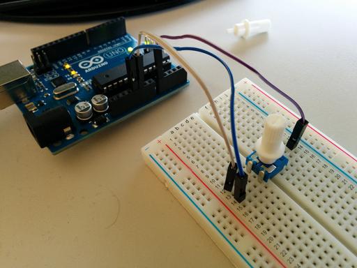
Next configure your hardware as shown in the image below. Typically a potentiometer has three pins: one for voltage in, one for ground and one
pin which corresponds to the variable resistor.


Next we need to connect Mathematica to the serial data link. This can be done with the following command:

serial = DeviceOpen["Serial", {"/dev/ttyACM0", "BaudRate" -> 115200}]


(When Mathematica 10 releases later this year, you can also run this experiment directly on a Windows or Mac computer, using for example the "COM" port on Windows).

Next we need to read the most current analog value.

ReadPotValue[] := Last[ DeviceReadBuffer[serial] ]


Now ReadPotValue[] will always return a current data value (like the number 157), so now we can read this value repeatedly using a ScheduledTask:

RunScheduledTask[val = ReadPotValue[], 0.33]


The 0.33 is the time interval here (3 times per second). On the Raspberry Pi this is close to the upper limit on how often you can read, especially when also running the next visualization step.

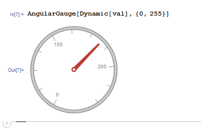
Finally you can visualize the current data value with an AngularGauge. Turning the potmeter connected to your Arduino will update the gauge in Mathematica:

AngularGauge[Dynamic[val], {0, 1023}]


Here is a video showing everything in action: http://www.youtube.com/watch?v=Ivzg5BY1GRw
POSTED BY: Arnoud Buzing
8 Replies

There is an updated version of this post available here.

POSTED BY: Ian Johnson

I am looking at the image an asking.. How are you connecting the ARDUINO to the Raspberry Pi? Are you using the USB port of the Pi to the USB of the Arduino or are you using cable from the TXT RCV pins? Can you show a better picture of this connection?

POSTED BY: Jose Calderon
Since this is a somewhat different topic, maybe you should make a new thread with a new title.
It would get more attention. (It would be fine to refer back to this thread, http://community.wolfram.com/groups/-/m/t/199023. )

Also, a little schematic drawing or explanation of how the photocell is hooked up might help.

p.s., RemoveScheduledTasks and RunScheduledTask start with capital Rs.  If the function
name shows as blue, it means the name is not defined.
POSTED BY: Bruce Miller
Posted 10 years ago
Also here is the Python sketch uploaded to the Arduino:
 int pin = 0;
 int val = 0;
 
 
 void setup(void)
     {
    
     Serial.begin(9600);
    
    }


void loop(void)
    {
   
        val = analogRead(pin);
        Serial.write(val);
        Serial.println(val);
        delay (1000);
       
    }
It appears to be working fine, but I wanted to include it in case there was something I should modify here.
POSTED BY: miles perry

My comment.. I think you are over killing with Serial.println(val); . Since you will see the data on the Mathematica notebook then why need to print to the monitor? Unless you assign to two different ports, you will not be able to see in Mathematica and at the same time in the Arduino IDE monitor.

POSTED BY: Jose Calderon
Posted 10 years ago
Alright, getting an output right now. When I do evaluate notebook it appears to only run once, give a unique reading and then stop. I am sure that the reading corresponds to the photosensor as when it is dark it reads 0 and light added displays a unique value for the amount of light. After displaying the unique value though, it ceases to create a unique value. Is there something else I need to do to run it repeatedly as shown in your writeup?

POSTED BY: miles perry
Posted 10 years ago
Thanks for the very detailed write up! 
I am trying to rig up a photocell with the following code but recieve the output at the bottom. Any idea where I went wrong?
 In[13]:= serial = DeviceOpen["Serial", {"COM4", "BaudRate" -> 9600}]
 
 
 Out[13]= DeviceOpen["Serial", {"COM4", "BaudRate" -> 9600}]
 
 
 In[14]:= removeScheduledTast /@ ScheduledTasks[];
 runScheduleTask[val = Last[DeviceReadBuffer[serial]], 2.00];
 

In[16]:= AngularGauge[Dynamic[val], {0, 1000}]


During evaluation of In[16]:= Part::partw: Part 2 of {COM4,BaudRate->9600} does not exist. >>


During evaluation of In[16]:= Part::partw: Part 2 of {COM4,BaudRate->9600} does not exist. >>
POSTED BY: miles perry
Here is another video with more details on the setup and using a simpler Arduino sketch which sends bytes directly without needing a ReadPotValue[] function:

http://www.youtube.com/watch?v=YpaNtyTTkqU
POSTED BY: Arnoud Buzing
Reply to this discussion
Community posts can be styled and formatted using the Markdown syntax.
Reply Preview
Attachments
Remove
or Discard

Group Abstract Group Abstract