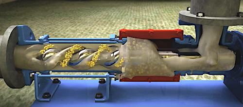
During all of history, people have looked for better ways to move water from one place to the other. This F.A.O. website gives an overview of the many screw pumps invented over the centuries. Some interesting examples are the Archimedes screw pump (left) from the 3rd century BC and the Moineau pump (right) patented in 1930.
The Moineau pump is a significant improvement over the Archimedes screw. The pump is called a "progressing cavity" pump. This means the pumped fluid is moving, without deformation through the pump .This leads to many applications in the food- and petroleum industry or where where exactly metered quantities are required. The Moineau pump is also a gem of 3D geometry for both its shape and its hypocycloid transmission. All of this makes it a perfect exercise to be explored with Mathematica! We look in detail at the two significant features of the pump: geometry and transmission. At the end, we put the two together in a working pump!
1. Geometry of the pump
The Moineau pump consists of two helical objects that can be defined as implicit regions:
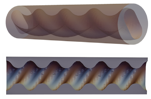
A static, hollow, helical casing with a stadium shaped cross section, called the stator.
stator = ImplicitRegion[
        Element[{x, y}, Disk[{0, 0}, 5]] &&
        Not[Element[{x, y},
        StadiumShape[2 {AngleVector[.5 z], AngleVector[.5 z + Pi]},
        2]]], {{x, -5, 5}, {y, 0, 5}, {z, 0, 12 Pi}}];
        RegionPlot3D[stator, PlotPoints -> 50,
        PlotStyle -> Lighter[Gray, .25], Boxed -> False,
        ViewVertical -> {1, 0, 0}]
This is the complete stator and a longitudinal cross cut showing an opened half of the stator:
2, Inside the stator is the rotor or a rotating helix with a circular cross section and with a pitch half that of the stator.
    RegionPlot3D[{stator, rotor}, PlotPoints -> 50,
     PlotStyle -> {Directive[Opacity[.99], Lighter[Gray, .05]],
       Lighter[Red, .25]}, ViewVertical -> {1, 0, 0}, Boxed -> False]
This shows how the rotor fits perfectly within the stator.
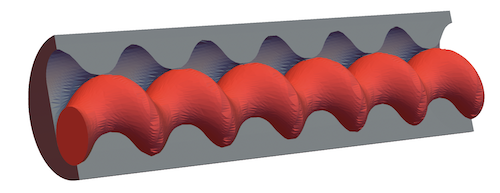
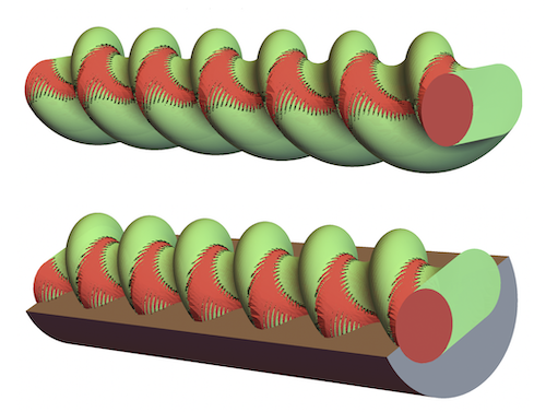
3, The cavities enclosed between stator and rotor are lenticular in shape and during operation, they will move in a helical motion and stay undeformed from inlet to outlet providing a uniform flow.
    cavity = ImplicitRegion[
       Element[{x, y},
         StadiumShape[2 {AngleVector[.5 z], AngleVector[.5 z + Pi]}, 2]] &&
         Not[Element[{x, y}, Disk[{1, 0} + AngleVector[z], 2]]], {{x, -4,
         4}, {y, -4, 4}, {z, 0, 12 Pi}}];
    RegionPlot3D[cavity, PlotStyle -> Lighter[Green, .5],
     ViewVertical -> {1, 0, 0}, Boxed -> False]
Show[cav,
 RegionPlot3D[stator, PlotPoints -> 50,
  PlotStyle -> Lighter[Gray, .25], Boxed -> False,
  ViewVertical -> {1, 0, 0}],
 RegionPlot3D[rotor, PlotPoints -> 50, PlotStyle -> Lighter[Red, .25],
   ViewVertical -> {1, 0, 0}, Boxed -> False]]
his shows the cavities wrapped around the rotor (top) and how rotor and cavities fill up the space in the stator (bottom). For clarity, only half of the stator is shown:
2. Hypocycloid Transmission
The rotor has to perform a hypocycloid rotation inside the stator. A point on a circle rolling inside another circle traces a hypocycloid. If the radius of rolling circle is half the radius of the larger circle, the hypocycloid becomes a straight line. If the tracing point is the center of another circle, this circle will move inside a stadium shape . Since the pump cross section is a stadium shape, this is exactly the mechanism we want.
Animate[Module[{ring, drive},
  ring = ParametricPlot3D[{2.01 Cos[u], 2.01 Sin[u], v}, {u, 0,
      2 Pi}, {v, -.98, 0}, PlotStyle -> Green, PlotPoints -> 25,
     PlotTheme -> "ThickSurface"][[1]];
  drive = {{Lighter[Blue, .6], Cylinder[{{1, 0, -1}, {1, 0, 0}}, 1]},
    Yellow, Cylinder[{{2, 0, 0}, {2, 0, .5}},
     1.75], {Lighter[Red, .15],
     Cuboid[{3.75, -.1, -.075}, {1.75, .1, 0.525}],
     Cuboid[{.9, -.1, -1.025}, {2, .1, +0.225}]}, {Lighter[
      Yellow, .15], Cylinder[{{1, 0, 0}, {1, 0, .15}}, .35]}};
  Graphics3D[{ring,
    Rotate[Rotate[{drive}, -phi, {0, 0, 1}, {1, 0, 0}],
     phi/2, {0, 0, 1}]}, PlotRange -> {{-4, 4}, {-3, 3}, {-2, 2}},
   Boxed -> False]], {phi, 0, 4 Pi, .01}]

3. Together as a working pump
We assemble the drive transmission with the pump and we see that the hypocycloid movement of the rotor fits exactly inside the stator.
Animate[DynamicModule[{ring, drive, statorBody, rotor},
  statorBody =
   RegionPlot3D[
     ImplicitRegion[
      Element[{x, y}, Disk[{0, 0}, 4.5]] &&
       Not[Element[{x, y},
         StadiumShape[2 {AngleVector[.5 z], AngleVector[.5 z + Pi]},
          2]]], {{x, -5, 5}, {y, 0, 5}, {z, 0, 12 Pi}}],
     PlotPoints -> 50,
     PlotStyle -> Directive[Opacity[.99], Lighter[Gray, .05]],
     Boxed -> False][[1]];
  rotor[t_] :=
   RegionPlot3D[
     ImplicitRegion[
      Element[{x, y},
       Disk[{Cos[z + phi/2] + Cos[phi/2], 2 Cos[(z + t)/2] Sin[z/2]},
        2]], {{x, -4., 4.}, {y, -4, 4.}, {z, -.05, 12 Pi}}],
     PlotStyle -> Lighter[Red, .35], Boxed -> False][[1]];
  ring = ParametricPlot3D[{2.01 Cos[u], 2.01 Sin[u], v}, {u, 0,
      2 Pi}, {v, -.98, 0}, PlotStyle -> Green, PlotPoints -> 25,
     PerformanceGoal -> "Quality", PlotTheme -> "ThickSurface"][[1]];
  drive = {{Lighter[Blue, .6], Cylinder[{{1, 0, -1}, {1, 0, 0}}, 1]},
    Yellow, Cylinder[{{2, 0, 0}, {2, 0, .15}}, 1.75], {Yellow,
     Cuboid[{3.75, -.1, -.075}, {1.75, .1, 0.525}], Red,
     Cuboid[{.9, -.1, -1.025}, {2, .1, +0.225}]}, {Lighter[
      Yellow, .15], Cylinder[{{1, 0, 0}, {1, 0, .15}}, 0.35]}};
  Graphics3D[{ring, statorBody, rotor[phi],
    Rotate[Rotate[{drive}, phi, {0, 0, 1}, {1, 0, 0}], -(phi/2), {0,
      0, 1}]}, Boxed -> False]], {phi, 0, -4 Pi, -.01}]
This is a ball moving through the pump showing the movement of fluid through the pump:
The trapped fluid will completely fill the cavities and this shows the pumping movement from left to right as the rotor rotates inside the stator in a hypocycloid motion:
cavity[phi_] :=
 RegionPlot3D[
   ImplicitRegion[
    Element[{x, y},
      StadiumShape[{{2 Cos[0.5` z],
         2 Sin[0.5 z]}, {-2 Cos[0.5 z], -2 Sin[0.5 z]}}, 2]] &&
     Not[Element[{x, y},
       Disk[{Cos[z + -phi/2] + Cos[-phi/2],
         2 Cos[(z - phi)/2] Sin[z/2]}, 2.]]], {{x, -4., 4.}, {y, -4.,
      4.}, {z, 0, 12 Pi}}], PlotStyle -> Lighter[Green, .5]] // First
For those interested, here is a short YouTube of a real working pump in action: