
All the above objects will reflect in a spherical mirror as the same virtual club suit image. They are part of an infinite number of anamorphic objects that will reflect to the same image. In this contribution,I will compute these objects with Mathematica, 3D print them and verify their reflection in a real mirror.
First, let us look at the geometry of reflection and anamorphosis in a spherical mirror:
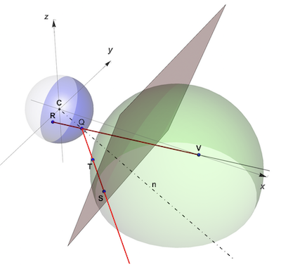
For both reflection and anamorphism, two surfaces and a viewpoint are needed:
a mirror surface, here a spherical mirror,
an anamorphic surface, this can be any surface outside the mirror. The points S and T are on two different anamorphic surfaces: S is on a plane parallel to the y-axis and T is on a sphere outside the mirror. A light ray emitted by S or T is reflected by the mirror at Q to meet the viewer's eye at V. The viewer at V sees both points S and T as the virtual point R. R is the reflection of both S and T in the mirror surface and S and T are the anamorphic maps of R. Any surface in the space x>1 can be an anamorphic surface and all of the points on the reflection line QTS that are outside the mirror are anamorphic map points of R.
the viewpoint can be any point along the x-axis outside both surfaces.
To write a function that computes the anamorphic image of a virtual point R in the mirror, we have to remember that: Anamorphism is "reverse engineering" of reflection! The desired reflection is a point R and we have to compute which points will reflect as R. A general function to compute the anamorphic map of a reflected point R would looks like this:

In the following function sphericAnamorphismMap we eliminate the choice of mirror surface and concentrate on spherical mirrors. Applying the law of reflection, this function computes the spherical anamorphic map of reflectedPoint R at {0, yr, zr} on an anamorphic surface anaSurface and observed from a viewPoint V on the x-axis at {xv, 0, 0}.
sphericAnamorphismMap[{yr_, zr_}, anaSurface_,
   xv_ : 10*^6] /; {yr, zr} \[Element] Disk[] :=
 Module[{ptV, ptR, ptQ},
  ptV = {xv, 0, 0}; ptR = {0, yr, zr};
  ptQ = {x, y, z} /.
    Last@NSolve[{{x, y, z} \[Element] Sphere[], {x, y, z} \[Element]
        HalfLine[{ptR, ptV}]}, {x, y, z}];
  NSolve[{{x, y, z} \[Element] anaSurface, {x, y, z} \[Element]
      HalfLine[{ptQ, ReflectionTransform[ptQ][-ptV]}]}, {x, y, z}][[1,
    All, -1]]]
We take the mirror surface to be a perfectly reflecting sphere of radius 1.
sphericMirror =
  Graphics3D[{Specularity[White, 50], Opacity[.4],
    SphericalPlot3D[1, {\[Theta], 0, Pi}, {\[Phi], -Pi/2, Pi/2},
      PlotStyle -> LightGray, PlotPoints -> 10,
      PerformanceGoal -> "Quality", Mesh -> None,
      Lighting -> "Accent"][[1]]}, Boxed -> False];
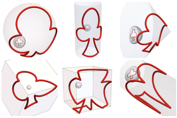
Any surface in the space x>0 can be used as an anamorphic surface. Here, we experiment with the following 6 surfaces:

(from left to right)
1: A concave (hemi)sphere with radius r, centered at {dx,dy,dz}:
sphereSurface[r_, offset : {dx_, dy_, dz_}] := Sphere[offset, r]
2: A vertical cylinder surface centered at {dx,dy,0} with axis parallel to the z-axis:
cylinderSurfaceV[r_, offset : {dx_, dy_}, h_] :=
 ImplicitRegion[(x + dx)^2 + (y + dy)^2 == r && -h < z < h, {x, y, z}]
3: A cone of height hc, base centered at {dx,dy,0} and with axis parallel to the x-axis :
    coneSurface[hc_, offset : {dx_, dy_}] :=
     ParametricRegion[{h, dx + (hc - h) Cos[\[Theta]],
       dy + (hc - h) Sin[\[Theta]]}, {{\[Theta], -2 Pi, 2 Pi}, {h, 0,
        hc}}]
4 and 5.: A set of 3 or 4 planes forming an open cube of n faces, translated by {xt, yt, zt} and rotated by {phiX, phiY, phiZ} around the three axes:
    cubeSurface[transl : {xt_, yt_, zt_}, \[Phi]x_, \[Phi]y_, \[Phi]z_,
      scale_, n_ : 3] :=
     Module[{cubepolys, transfoFun},
      cubepolys = PolyhedronData["Cube", "Polygons"];
      transfoFun =
       Composition[TranslationTransform[transl],
        RotationTransform[\[Phi]x, {1, 0, 0}],
        RotationTransform[\[Phi]y, {0, 1, 0}],
        RotationTransform[\[Phi]z, {0, 0, 1}],
        ScalingTransform[{scale, scale, scale}]];
      RegionUnion[Map[transfoFun, cubepolys[[;; n]], {3}]]]
6: A horizontal cylinder centered on the x - axis and with a radius r> 1 and height h:
    cylinderSurfaceH[r_, h_] :=
     ImplicitRegion[y^2 + z^2 == r^2, {{x, 0, h}, y, z}]
We take three simple images that fit inside our spherical mirror as reflected images. The images consist of a list of point coordinates: clubPts, wolfPts and piPts.To improve smoothness in sharp corners (especially with discontinuous surfaces such as cube) , we use an interpolation function interpol to reduce and equalize the distance between each couple of points.
interpol[{pt1 : {x1_, y1_}, pt2 : {x2_, y2_}}, d_ : 0.1] :=
 Module[{n}, n = EuclideanDistance[pt1, pt2]/d + 1*^-6;
  Table[(1 - t) pt1 + t pt2, {t, 0, 1, 1/n}]]
mcClub = MeshCoordinates[
   BoundaryDiscretizeGraphics[Text[Style["\[ClubSuit]", Bold]], _Text,
     MaxCellMeasure -> 0.1]]/8; clubPts = Append[mcClub, First@mcClub];
mcWolf = MeshCoordinates[
    BoundaryDiscretizeGraphics[Text[Style["\[Wolf]", Bold]], _Text,
     MaxCellMeasure -> 0.1]]/7;
wolfOrder = FindShortestTour[mcWolf];
wolfPts =
 Flatten[interpol[#, .03] & /@
   Partition[
    Drop[Drop[mcWolf[[Last[wolfOrder]]]/1.5, {45, 48}], {137, 146}],
    2, 1], 1]; mcPi =
 MeshCoordinates[
   BoundaryDiscretizeGraphics[Text[Style["\[Pi]", Bold]], _Text,
    MaxCellMeasure -> 0.1]]/
  8; piPts = .95 Flatten[
   interpol[#, .02] & /@
    Partition[Append[mcPi, First@mcPi], 2, 1, {1, 1}], 1];
GraphicsRow[
 MapThread[
  Graphics[{Circle[], #2, Point[#1]}] &, {{clubPts, wolfPts,
    piPts}, {Red, Blue, Green}}]]

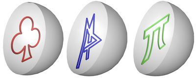
These are the three virtual images we want to see reflected in the spherical mirror:
clubReflection = Tube[clubPts /. {x_, y_} -> {0, x, y}, .025];
wolfReflection = Tube[wolfPts /. {x_, y_} -> {0, x, y}, .02];
piReflection = Tube[piPts /. {x_, y_} -> {0, x, y}, .02];
reflections = {clubReflection, wolfReflection, piReflection};
Row[MapThread[
  Show[sphericMirror, Graphics3D[{#2, #1}],
    ImageSize -> 150] &, {reflections, {Red, Blue, Green}}]]
The following Graphics3D are the anamorphic maps of the club suit image for the 6 different surfaces. These objects are in fact 3D curves using Tube as a Graphics Directive:
surfaces = {sphereSurface[4, {1.35, 1.25, 1.75}],
   cylinderSurfaceV[12, {-1, 0}, 7], coneSurface[4, {1, 1/2}],
   cubeSurface[{-3, 0, 0}, -1/2, Pi/4, -Pi/4, 18, 3],
   cubeSurface[{2, 3/2, 0}, 1/5, 0, -Pi/2, 10, 5],
   cylinderSurfaceH[2, 10]};
radii = {.12, .2, .09, .35, .22, .1};
Module[{pts, surf},
 pts[s_] := sphericAnamorphismMap[#, s, 15] & /@ (0.85 clubPts);
 surf[s_] := Region[Style[s, Opacity[.1]]];
 Grid[Partition[
   MapThread[
    Show[sphericMirror, surf[#1],
      Graphics3D[{Red, clubReflection, Tube[pts[#1], #2]},
       ImageSize -> 200]] &, {surfaces, radii}], 3, 3]]]
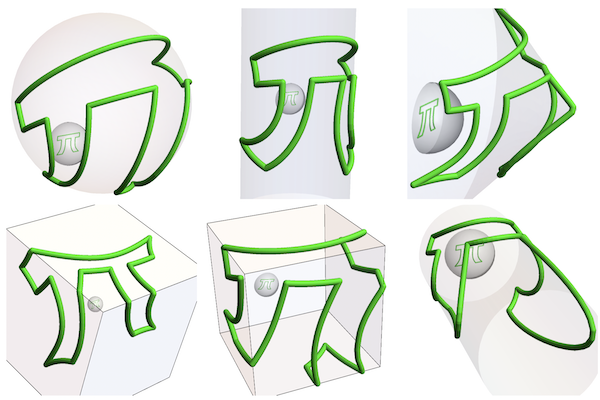
Using the same code with piPts:
I looked for at least one object to make with 3D printing and test it in a real setting. To make the illusion between a strangely deformed object and its simple reflection more extreme, I selected a cube surface sufficiently rotated {1/5,0,-Pi/2} and translated {2, 3/2, 0} to produce a sufficiently deformed anamorphic object. These are the anamorphic maps of the three reflections on the selected cube surface:
points = {clubPts, wolfPts, piPts};
colors = {Red, Blue, Green};
With[{s = cubeSurface[{2, 3/2, 0}, 1/5, 0, -Pi/2, 10, 5]},
 Row[MapThread[
   Show[(*sphericMirror,*)Region[Style[s, Opacity[.2]]],
     Graphics3D[{#2,(*#3,*)
       Tube[ParallelMap[
         sphericAnamorphismMap[#1, s, 15] &, #], .25]}],
     ImageSize -> 200, ViewPoint -> {5, -1, 0}] &, {.95 points,
    colors, reflections}]]]

Here is the selected clubModel to 3DPrint: an anamorphic 3D curve on a cube surface that reflects as a simple club suit in a spherical mirror:
Module[{cubepolys, anaSurface, clubPtsX, anaClubPts},
 cubepolys = PolyhedronData["Cube", "Polygons"];
 anaSurface = cubeSurface[{.1, 0, -.2}, 1/5, 0, -\[Pi]/2, 4, 5];
 clubPtsX =
  Flatten[(interpol[#1, .25] &) /@ Partition[clubPts, 2, 1], 1];
 anaClubPts =
  ParallelMap[sphericAnamorphismMap[#1, anaSurface, 10] &, clubPtsX];
 Show[Graphics3D[{{Opacity[.25], Sphere[]}, {Red,
     Tube[clubPtsX /. {y_?NumericQ, z_} -> .97 {0, y, z}, .025]}}],
  clubModel =
   Graphics3D[{Red,
     Tube[BSplineCurve[anaClubPts, SplineClosed -> True], .075]}],
  Region[Style[anaSurface, Opacity[.35]]], Boxed -> False]]
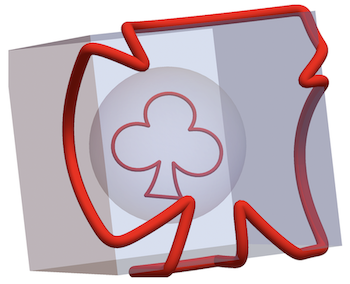
This creates an STL file of our clubModel to be sent to Sculpteo: for 3D printing:
Printout3D[clubModel, NotebookDirectory[] <> "clubmodel-2.stl",
 RegionSize -> Quantity[10, "cm"]]
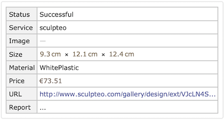
To find the real size of the model to order from Sculpteo, we multiply the dimensions of the Graphics3D model by the radius of the mirror (30 mm). We entered the following measurements the in the Sculpteo website:
30*Round[#, .1] & /@
  Abs@Apply[Subtract,
    MinMax /@ Transpose[anaClubPts], {1}] // Rasterize

This is a link to the "3D print Dossier by Sculpteo".
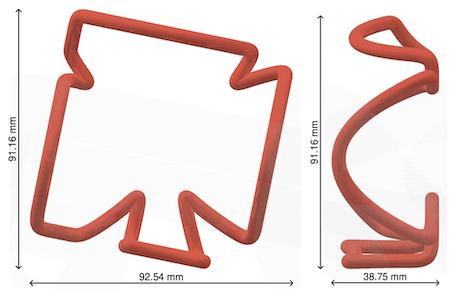
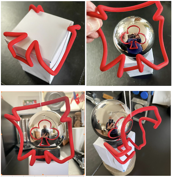
These are photos of the 3D printed result showing how the printout fits on a cubic surface and when rotated and translated correctly, it reflects as the intended image! We attached the STL file "clubmodel-2.stl" of this model at the end of this communication.
If we use a horizontal cylinder cylinderSurfaceH as anamorphic surface, the distance between the anamorphic tube coordinates and the viewpoint varies substantially. To compensate for the diminishing perspective, we create a function radiusCompFun to change the Tube radius in function of the distance from the origin. This way, the Tube radius will increase proportionally as a piece of tube gets farther away from the viewpoint.
radiusCompFun[pointLst_, base_, rate_] :=
 Module[{n, offset}, n = Length@pointLst;
  offset = Part[MinMax /@ Transpose[pointLst], 1, 1];
  base + 2 rate Table[pointLst[[i, 1]] - offset, {i, n}]]
pointLst is a list of 3D points that define the Tube, base is the starting radius closest to the origin and rate is the rate of radius increase as we get further the viewpoint. The following anamorphic object consists of Tube primitives with varying radius and, if rate is properly selected, it should reflect as an original with constant radius.
Module[{mcClub, clubPts, anaSurface, anaClubPts},
 mcClub =
  MeshCoordinates[
    BoundaryDiscretizeGraphics[
     Text[Style["\[ClubSuit]", Bold]], _Text, MaxCellMeasure -> 0.1]]/
   8; clubPts =
  Flatten[interpol[#, .02] & /@
    Partition[Append[mcClub, First@mcClub], 2, 1, {1, 1}], 1];
 anaSurface = cylinderSurfaceH[2, 6];
 anaClubPts =
  ParallelMap[sphericAnamorphismMap[#, anaSurface, 10] &, clubPts];
 Show[sphericMirror, Region[Style[anaSurface, Opacity[.35]]],
  Graphics3D[{Red,
    Tube[BSplineCurve[
       clubPts] /. {y_?NumericQ, z_} -> .97 {0, y, z}, .04],
    Tube[BSplineCurve[anaClubPts, SplineClosed -> True],
     radiusCompFun[clubPts, .06, .03]]}, Boxed -> False,
   Lighting -> "Accent"], ViewPoint -> {1.5, 0, 0}]]
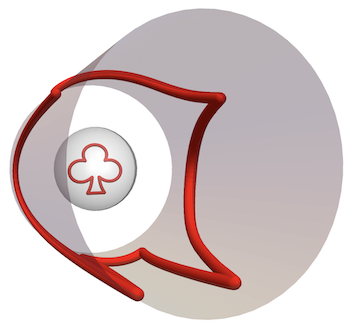
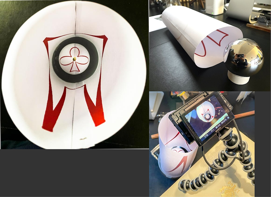
It is too expensive for me to 3DPrint all these objects so I resorted to replacing the Tube sections by Line primitives. This way, the output can be printed on paper and the anamorphic surface can simply be rolled as a cylinder. For the development along the cylindrical wall, we use thicknessCompFun to set the variable thickness of the line in the x-direction:
thicknessCompFun[pointLst_, base_, rate_] :=
 base + rate pointLst[[-1, -1]]
offsetFun[x_] := If[x < -Pi/2, x + 2 Pi, x];
Module[{mcClub, clubPts, anaClubPts},
 mcClub =
  MeshCoordinates[
    BoundaryDiscretizeGraphics[
     Text[Style["\[ClubSuit]", Bold]], _Text, MaxCellMeasure -> 0.1]]/
   8; clubPts =
  Flatten[interpol[#, .02] & /@
    Partition[Append[mcClub, First@mcClub], 2, 1, {1, 1}], 1];
 anaClubPts =
  ParallelMap[sphericAnamorphismMap[#, cylinderSurfaceH[2, 10], 10] &,
    clubPts];
 Graphics[Map[{Red, AbsoluteThickness[thicknessCompFun[#, 3, 2]],
     Line[#]} &,
   Select[Partition[
     anaClubPts /. {x_?NumericQ, y_, z_} -> {offsetFun@ArcTan[y, z],
        x}, 2, 1], EuclideanDistance @@ # < 5 &]]]]
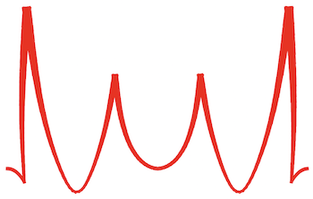
These are photos of the cylinder with the anamorphic curve printed inside and reflected in the spherical mirror. One observes that due to the thickness compensation, the reflected image has constant thickness notwithstanding the diminishing perspective:
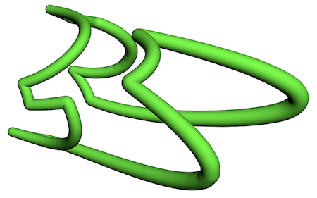
For the same image in 3D printing, we have to use our radius compensation function radiusCompFun:
Module[{mcPi, anaPiPts},
 anaPiPts =
  ParallelMap[sphericAnamorphismMap[#, cylinderSurfaceH[2, 10], 10] &,
    piPts];
 PiModel =
  Graphics3D[{{Green,
     Tube[BSplineCurve[anaPiPts, SplineClosed -> True],
      radiusCompFun[anaPiPts, .12, .012]]}}, Boxed -> False]]
Here is a simulation in Graphics3D how the complete setup, including reflection, would look like:
Module[{anaPiPts},
 anaPiPts =
  ParallelMap[sphericAnamorphismMap[#, cylinderSurfaceH[2, 20], 10] &,
    piPts];
 PiModel =
  Show[Graphics3D[{{Green,
      Tube[BSplineCurve[anaPiPts, SplineClosed -> True],
       radiusCompFun[anaPiPts, .1, .01]]}}, Boxed -> False],
   Graphics3D[{{{Opacity[.2], Sphere[]}, {Opacity[.15], LightBlue,
       Cylinder[{{0, 0, 0}, {10, 0, 0}}, 2]}, {Green,
       Tube[BSplineCurve[piPts /. {x_?NumericQ, y_} :> {0, x, y},
         SplineClosed -> True], .05]}}}, Boxed -> False],
   ViewPoint -> {1.5, 0, 0}]]
Attached is the 3D print files "clubModel.stl" and "piModel.stl" if you want to test this yourself!
 Attachments: