Back in 1638, Minim Father Jean François Niceron wrote a ground-breaking book for architects and artists alike: "La Perspective Curieuse". In this book he describes the mathematical methods to obtain drawings and paintings using perspective, catoptric anamorphism (with cylindrical and conical mirrors) and dioptric anamorphism by means of refraction in crystals.
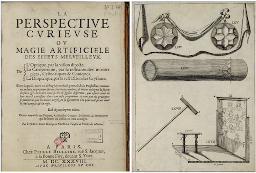
The refractive telescope in the above illustration used a polyhedral lens consisting of 8 crystals and was meant to recompose 8 pictures into a single one by means of refraction. Although a digital reconstruction of the apparatus exists, the actual telescope was lost in a Venice flood. It would be a mathematical tour de force to study the mathematics of the refractive optics through the multi faced lens. To get a feel of what is refractive anamorphism (contrary to catoptric anamorphism), I made a short study about anamorphism by means of refraction in a cylinder filled with a sugar solution. The crystals used by Niceron had a refractive index of at least 1.55. The highest index I could obtain was 1.448 by using a 65% sucrose solution inside a cylindrical glass. Let us first see what we can do with Mathematica to emulate refraction through a solution filled cylinder and create a dioptric anamorphic image.
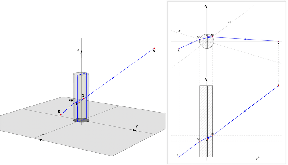
The above optical ray diagrams show a 3D view (left) and a 2D horizontal {top right) and vertical (bottom right) cross section. A ray leaving the point R in the x-y plane will meet the viewer's eye at V. This after being refracted at intersection points Q2 between air and cylinder liquid and Q1 between liquid and air. The resulting light ray from V to R is a combination of: 1. refraction in the horizontal plane through Q1 and Q2 (top right) and 2. refraction in the vertical plane through Q1 and Q2 (bottom right). The result is that the viewer sees the point R in the x-y plane as a virtual point P in a view plane inside the cylinder. R can be defined as the dioptric (refractive) anamorphic of P or, inversely, P can be defined as the refracted image of R. In both cases, Snell's law of refraction applies:
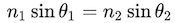
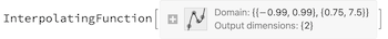
n1 and n2 are the two refractive indices: 1.448 for air -> sucrose solution and 1/1.448 for sucrose solution -> air. Theta 1 and Theta 2 are the incident and refracted angles. Since the relation between anamorphic points R and virtual points P is rather complex, we use an interpolation function ifR to compute the coordinates of R in the x-y plane from the coordinates of P in the view plane. The following code makes a table tblR of R and P coordinates using Snell's law and plain geometry. The interpolation function ifR is derived from the data in tblR:
tblR = With[{c = 1, yv = 10, zv = 10,
    nr = 1.448},(*the cylinder radius is 1 and the viewpont is at {10,
   0,10)*)
   ParallelTable[
    Quiet@
     Module[{yc, ptVh, ptVv, ptPh, ptPv, ptQ1h, ti1, tr1, ti1v, tr1v,
       ptQ2h, ti2, tr2, ti2v, tr2v, ptQ1v, ptQ2v, ptRv, ptR},
      (*view plane location and width*)yc = c^2/yv;
      wi = Round[c Sqrt[1 - c/yv^2], .001];
      ptVh = {yv, 0}; ptPh = {yc, xp}; ptVv = {yv, zv};
      ptPv = {yc, zp};
      (*HORIZONTAL SECTION*)
      (*incoming intersection point Q1*)
      ptQ1h =
       First@
        NSolveValues[{Element[{x, y}, Line[{ptPh, ptVh}]] \[And]
           x^2 + y^2 == c^2}, {x, y}];
      (*angle of incidence*)ti1 = VectorAngle[ptVh - ptQ1h, ptQ1h];
      (*angle of refraction*)tr1 = Sign[xp] ArcSin[Sin[ti1]/nr];
      ptQ2h =
       First@
        SortBy[
         NSolveValues[{Element[{x, y},
             InfiniteLine[
              ptQ1h, -AngleVector[-tr1 + ArcTan @@ ptQ1h]]] \[And]
            x^2 + y^2 == c^2}, {x, y}], First];
      (*outgoing intersection point Q2*)
      (*angle of incidence*)
      ti2 = tr1;
      (*angle of refraction*)tr2 = ArcSin[Sin[ti2]*nr];
      (*VERTICAL SECTION*)
      (*incoming ray*)
      \
(*intersection point*)
      ptQ1v =
       First@
        NSolveValues[{Element[{x, y}, Line[{ptVv, ptPv}]] \[And]
           x == ptQ1h[[1]]}, {x, y}];
      (*angle of incidence*)ti1v = VectorAngle[ptVv - ptQ1v, {1, 0}];
      (*angle of refraction*)tr1v = -ArcSin[Sin[ti1v]/nr];
      (*outgoing ray*)
      (*intersection point*)
      ptQ2v =
       First@
        NSolveValues[{Element[{x, y},
            HalfLine[ptQ1v, {-1, Tan[tr1v]}]] \[And]
           x == ptQ2h[[1]]}, {x, y}];
      (*angle of incidence*)ti2v = tr1v;
      (*angle of refraction*)tr2v = ArcSin[Sin[ti2v]*nr];
      ptRv =
       First@
        NSolveValues[{Element[{x, y},
            HalfLine[ptQ2v, {-1, Tan[tr2v]}]] \[And] y == 0}, {x,
          y}];
      ptR =
       Last@
        NSolveValues[{Element[{x, y},
            InfiniteLine[ptQ2h,
             AngleVector[tr2 + ArcTan @@ ptQ2h]]] \[And]
           x == ptRv[[1]]}, {x, y}];
      {{xp, zp}, ptR}], {zp, .75, 7.5, .05}, {xp, -.99, .99, .02}]];
ifR = Interpolation[Flatten[tblR, 1]]
Below, we apply the function ifR to a set of concentric circles in the view plane and compute the corresponding refractive anamorphic mapping in the x-y plane. The hatched disk is the cross section of the cylinder and shows its relative size and position.
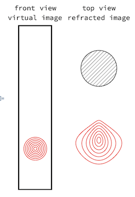
Using the same function ifR, we can make an animation in 3D of a point rotating around a circle in the view plane and see it traveling around the circle's refractive anamorphic image in the x-y plane:
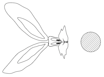
We are now ready to experiment with some real images. The first trial is with the the "Bugs Bunny" popular curve. We map the function ifR to the point coordinates and get the refractive anamorphic image:
centerAndScale[g_] :=
 Module[{lns, pts, xMin, xMax, yMin, yMax, centeredLns, scaledLines},
  lns = Cases[g[[1]], _Line, \[Infinity]];
  pts = Flatten[lns[[All, 1]], 1]; {xMin, xMax} =
   MinMax[pts[[All, 1]]]; {yMin, yMax} = MinMax[pts[[All, 2]]];
  centeredLns = Map[#1 - {(xMax + xMin)/2, +yMin} &, lns, {3}];
  Map[1.35` #1/Abs[xMax - xMin] &, centeredLns, {3}]]
bugsbunnyPrimitives =
  centerAndScale[
    First[
     ParametricPlot[
      Entity["PopularCurve", "BugsBunnyCurve"]["ParametricEquations"][
       t], {t, 0, 40 \[Pi]}]]] /. {x_?NumericQ, y_?NumericQ} :>
    1.35 {x, 1.05 y + 1};
refractedPrimitives = MapAt[ifR @@ # &, prims, {All, 1, All}];
Graphics[{{HatchFilling[], Disk[]}, Circle[], AbsoluteThickness[1],
  refractedPrimitives}, Axes -> False, Ticks -> None,
 AxesOrigin -> {0, 0}]
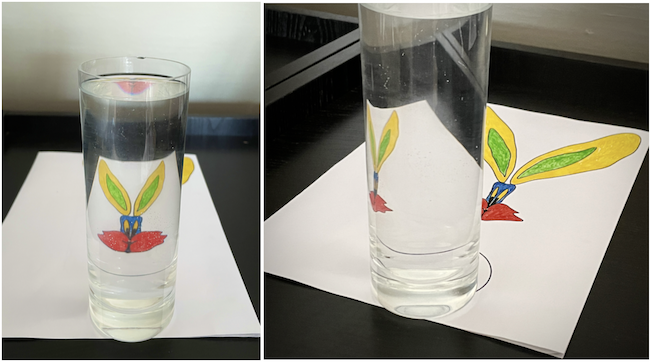
Below demonstrates how the printout of the anamorphic image looks like the original after refraction through a glass filled with a sucrose solution:
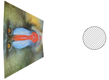
The same can be done with any photographic image. We use the function ImageSquareDivide from the Wolfram Function Repository to divide the image into a set of colored polygons and map the function ifR to the coordinates of polygon's vertices:
mandrill = ImageResize[ExampleData[{"TestImage", "Mandrill"}], 50];
gr = ResourceFunction["ImageSquareDivide"][
    mandrill] /. {x_, y_} -> .7 {x, y + 5};
Graphics[gr, Axes -> True, AxesOrigin -> {0, 0}];
grR = Quiet@MapAt[ifR @@ # &, gr, {All, -1, 1, All}];
Graphics[{{HatchFilling[], Disk[]}, Circle[], grR},
 AxesOrigin -> {0, 0}]
Here again, we see the original image after refraction of the anamorphic printout:
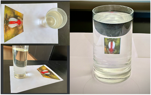
Refraction does not result in the strong deformations obtained by reflection in cylindrical mirrors. The use of polished glass lenses or crystals as documented by Niceron would undoubtedly result in more spectacular results.


