This is a sister thread of
a discussion about Hodgkin-Huxley cable (HHC) simulation. I am writing this companion article here to show how to use
Wolfram SystemModeler to recreate this physical system and make it easier to use in the future as black box.
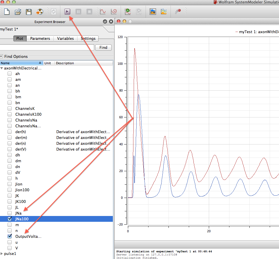
Lets first take a look at my result. The graph on the left is written in Mathematica from this Demonstrations web page:
The Hodgkin-Huxley Equations for Transmission of Electrical Impulses along an Axon
The result on the right hand side from
my SystemModeler model (download and unzip everything, open mytest.mo with SystemModeler). The parameters are set with stimulus = 0.142 (mA/cm^2), start time = 1 ms and duration = 40 ms. You can find the two results are identical after you exam the characteristics of the two curves.
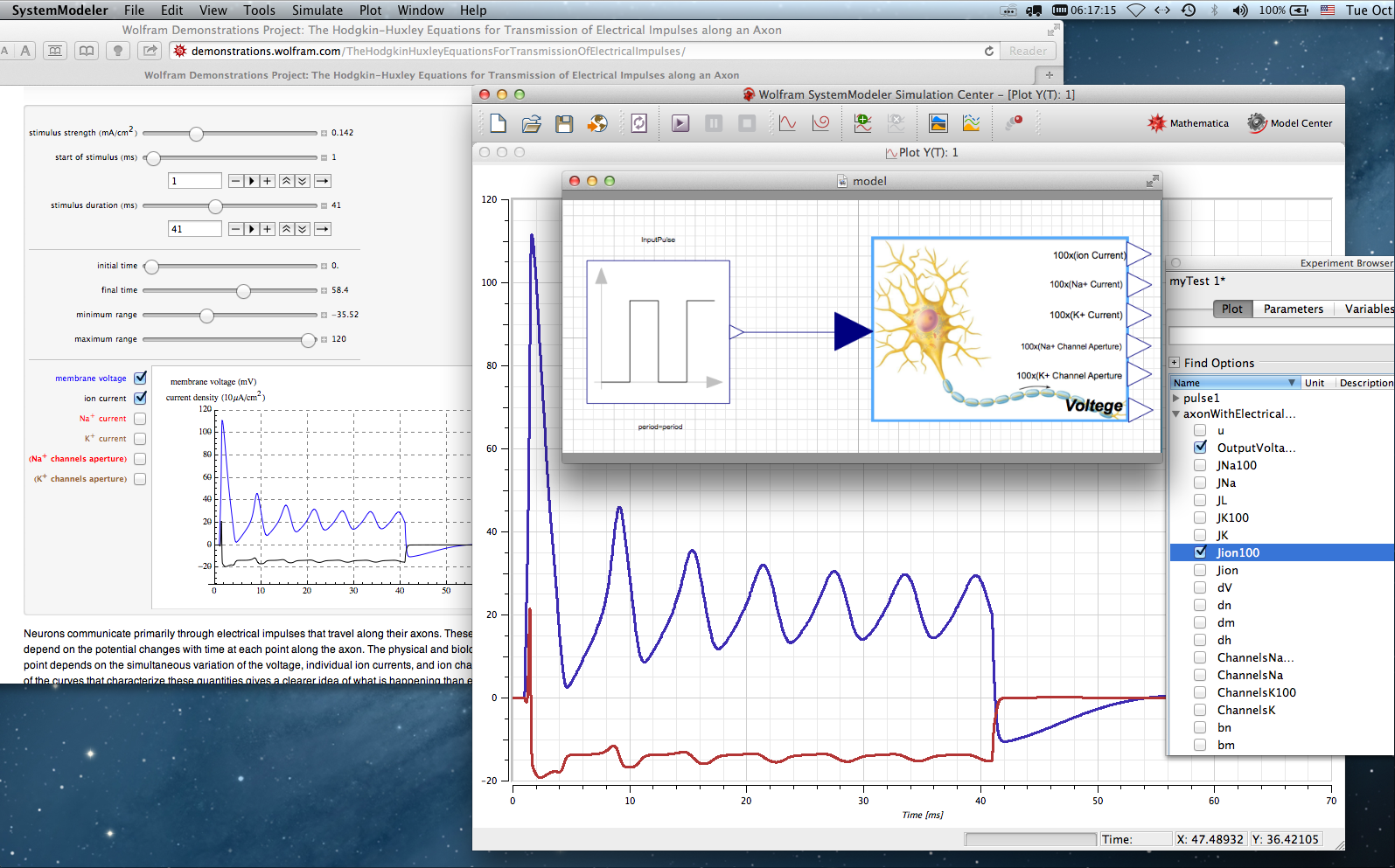
Of course the Manipuate function in Mathematica is very powerful, yet SystemModeler creates a compoent-like element, which is more convenient to use and more adaptive to a larger set. Another great advantage is that System Modeler encapsulates your code to high level so products should not contain any codes other than the neat blocks or flow charts.
Though you may be told that you can draw an equivalent circuit to simulate the HHC, we here demonstrate a hardcore-yet-very-general instruction so that you can convert your other Mathematica codes nto a System modeler examples.
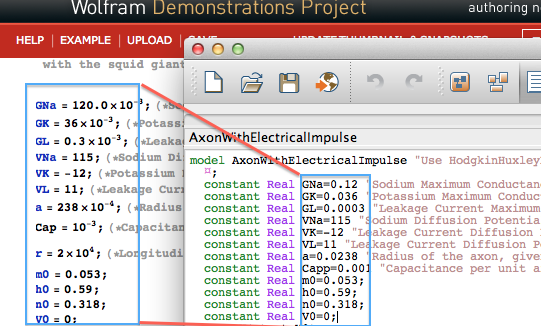
In Faria's notebook you may first uncollapse the Initialization Code section. There are many constants defined ahead of the following calcualation. In system modeler I do the following: use keywords "constant" to declare a symbol that is not going to changel; "Real" is simply a type of the symbol, which is like float or doulble in C/C++.
The next step is to define those intermediate functions. Because these functions are rather simple, I just sneak around and take advantage of variables in SystemModeler to handle these one-argument dependencies. I use "Real am;", for instance, to delcare such a variable that is indeed a function of V (which in turn depends on time T). In System modeler, a variable is simply a symbol whose value can be changed during computation.
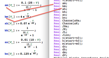
After I have declared those symbols, I put all denitions into the equation section. For example, "am" can just be replaced with a algebraic expression with respect to V. This also applies to the rest variables or my original Mathematica function heads.
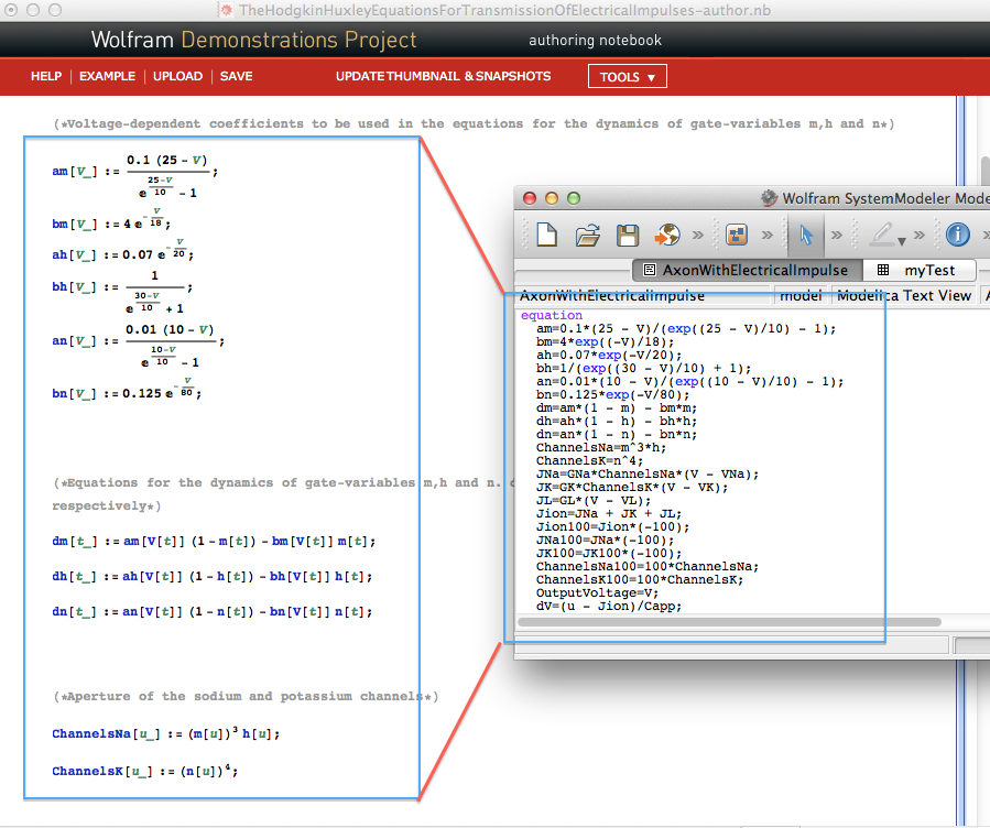
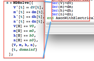
I also notice that the value of V, m, h and n are determined via a system of differential equations. In System Modeler the keyword "der" indicates the first order differential wrt time. It cannot be used recursively, that is No "der(der(x))".
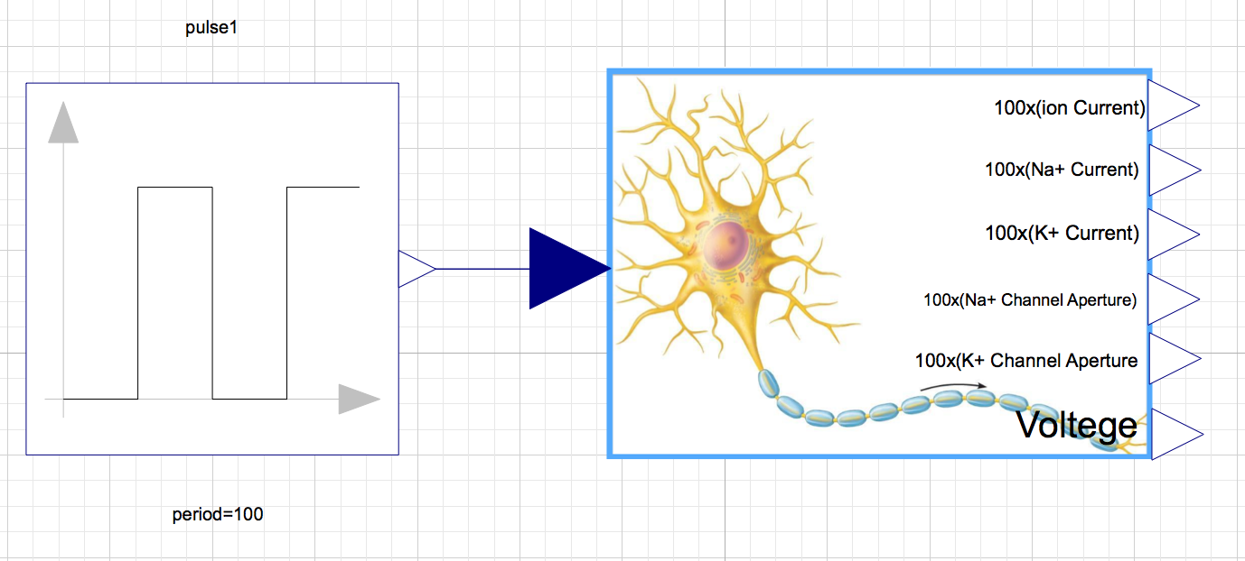
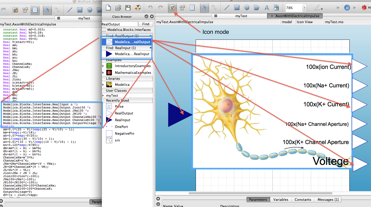
I think one of the most featured parts is that I can use GUI to program at same time. The "Modelica.... RealInput" symbols are such drag-drop components. These componts works as a liason so the values inside my axon cable model can talk to other models/blocks and recieve information at the same time. In this case, I just make a copy of the "RealInput" class (dark blue) and "RealOutput" class (white) into my model. If you look closely at the code, you should see a small blue icon on the right end of the framed code block. It is a collapsed symbol for annotation, which contains the coordinates and other graphical info for each compoent when printed on the workspace.
So far I have walked you through the main process of converting the demonstration project in Mathematica to Systemmodeler language. You can
download the entire model with a compiled experimental file, *.sme file. With either option, you need to hit the play button to run the experiment and uncollapse the argument list to pick up the output you want to see in the plot, just like the attachment below.
Certainly I left you something to explore such as how to add a picture into the model. Since you have my model, you can spend some time to work around and explore the new things as an essential part of learning.
Ref.
The big and juicy picure of the neuron cell which I used in the model is
from this web page.


