Message Boards Message Boards

1
|
5898 Views
|
12 Replies
|
4 Total Likes
View groups...
Share
Share this post:

How to draw real world image size?

Posted 5 years ago

I want to print a Graphics with a given absolute width and height in say, millimeters.

From the reference documentation of Graphics, I understand that in:

ImageSize->w

w is required in points or 1/72 inch. If w shall be in millimeters, hence I have to write:

ImageSize->360/127 w

But this does not work. It leads to a far smaller image when printed.

Can anybody tell me, how to specify options for drawing images with given real-world size? Or, even better, can someone point me to a description how WL deals with sizes of drawings, frames, panes, margins, padding, etc.?

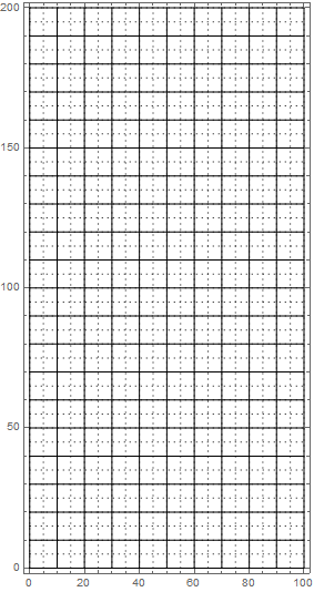
Here a small example that should draw a Graphics with absolute width w mm and height h mm. It has a raster of centimeter lines and dotted m-millimeter lines.

draw[w_, h_, m_: 1] :=
 Graphics[{Thin,
   (* draw mm-lines every m millimeters *)
   Dotted,
   Table[Line[{{x, 0}, {x, h}}], {x, 0, w, m}],
   Table[Line[{{0, y}, {w, y}}], {y, 0, h, m}],
   (* draw cm-lines *)
   Dashing[{}],
   Table[Line[{{x, 0}, {x, h}}], {x, 0, w, 10}],
   Table[Line[{{0, y}, {w, y}}], {y, 0, h, 10}]
   }, Frame -> True, ImageSize -> 360/127 w, AspectRatio -> h/w
  ]

Block[{g, tmp},
 g = draw[100, 200, 5];
 Print[g]; 
 Print[tmp = AbsoluteOptions[g, ImageSize], "\t", 
  tmp = Quantity[Last[tmp[[1]]], "points"], "\t", 
  UnitConvert[tmp, "millimeter"]]
 ]

enter image description here

{ImageSize->283.465}    283.465pt  100.mm

When I print those graphics on my HP LaserJet the raster is 64mm wide and 131mm high. I would expect that to be 100mm and 200mm. The surrounding frame is 67mm wide and 134mm high.

POSTED BY: Werner Geiger
12 Replies

Hi Werner,

I've just tried printing to paper and get the correct sized plot - see image below.

enter image description here

I've also removed the unnecessary code from the chopped notebook I sent previously. The revised notebook, with just two additional one-line cells in the stylesheet, is attached. This should be easier to follow. If you haven't already done so, it'd be worth taking a look at the documentation for Magnification.

All the best,

Ian

Just to add that the scaling factor of 72/100 mentioned in your earlier posting arises because Magnification for the Printout environment is set to 0.72 in the Default stylesheet - see screenshot below. Resetting this to 1.0 goes part way to resolving your problem. You also need to avoid, or overcome, the scaling that can arise due to the effects of other things such as PlotRangePadding, the inclusion of ticks, tick labels and axis/frame labels, etc. All of which shrink the actual graphics area within the overall ImageSize. The easiest thing to do is just to make sure all such effects are turned off.

enter image description here

POSTED BY: Ian Williams
Posted 5 years ago

Great, Ian, thanks a lot. You have boiled down the problem to its kernel.

The inclusion of ticks, tick labels, axis/frame/plot-labels, insets, etc. is another problem. PlotRange does not help. Probably PlotRangePadding, ImagePadding, ImageMargins with some calculations would solve it.

Actually, what is missing, is a PlotSize-Option or the like that tells the size of the plotted axes, leaving out all adornments around the plotted graphics primitives. Other graphics applications have something like a drawing area for that which can be directly sized.

POSTED BY: Werner Geiger

Hi Werner,

I've just tried printing to paper and get the correct sized plot - see image below.

enter image description here

I've also removed the unnecessary code from the chopped notebook I sent previously. The revised notebook, with just two additional one-line cells in the stylesheet, is attached. This should be easier to follow. If you haven't already done so, it'd be worth taking a look at the documentation for Magnification.

All the best,

Ian

Attachments:
POSTED BY: Ian Williams

Hi Werner,

No problem. The stuff I posted was chopped out of a bigger stylesheet I use and contains elements that aren't strictly necessary. All you really need is...

   Cell[StyleData[All, "Printout"], Magnification -> 1.0]

and possibly...

  Cell[StyleData[All, "Working"] , Magnification -> 1.0 ]

if you want your graphics to line up with the ruler in the working environment. The easiest way to add these lines is via the stylesheet editor menu. I chosen not to use Mathematica's Quantity functions for this straightforward application as the conversions are very simple.

Hope this helps,

Ian

POSTED BY: Ian Williams

I've had chance to look at your example in a bit more detail. Does this do what you want?

draw[w_, h_, m_: 1] := Module[
  {mm = 72.0/25.4}
  , Graphics[
   {
    (*draw mm-lines every m millimeters*)Thin, 
    Table[Line[{{x, 0}, {x, h}}], {x, 0, w, m}], 
    Table[Line[{{0, y}, {w, y}}], {y, 0, h, m}],(*draw cm-lines*)
    Thickness[Medium], Table[Line[{{x, 0}, {x, h}}], {x, 0, w, 10}], 
    Table[Line[{{0, y}, {w, y}}], {y, 0, h, 10}]}, Frame -> True, 
   FrameTicks -> None, ImageSize -> {w*mm, h*mm}, 
   PlotRange -> {{0, w}, {0, h}}, PlotRangePadding -> None]
  ]

draw[100, 200, 2]

You'll need to use the stylesheet produced by the notebook attached to my previous reply.

Again, I haven't printed to paper, but looks right when viewed against Mathematica's ruler - see screenshot below.

enter image description here

I'm not sure how it would work if you want/need the frame labels - maybe look at options such as PlotRangePadding, etc...

Hope this helps,

Ian

POSTED BY: Ian Williams
Posted 5 years ago

Thanks, Ian, for your help.

I think your program is exactly the same as mine. As I told in my previous reply to you some minutes ago, the problem does not ly within the program coding, but within the style sheet only.

We can forget about that draw-mm-paper program. Your small draw-a-rectangle is much better suited to isolate my problem.

Best regards, Werner

POSTED BY: Werner Geiger

Does the attached notebook help?

It draws a 100mm wide by 50mm high rectangle. I haven't printed out to paper, but Mathematica's ruler bar suggests that the rectangle is drawn at the correct size - see screenshot below.

enter image description here

All the best,

Ian

Attachments:
POSTED BY: Ian Williams
Posted 5 years ago

Thanks very much, Ian. This helped although I don't understand it.

  1. The rulers don't help. They show sizes as defined in the program but not in real-world measures when printed. Of course, your program shows the correct size. So does my draw-mm-Paper program from above. The problem starts when it comes to printing.

  2. If I just copy your 4-liner-program without your style options into my notebook and run it, it shows a rectangle of width 100 according to the ruler. But when printed it becomes 72 mm x 36 mm only! Hence it is too small by a factor of 72/100. This is my problem.

  3. If I run your complete RealWorldSize program including the style options, it shows the same but prints correctly 100 mm x 50 mm!

  4. If I copy your style options into my notebook everything shows as before but prints correctly!

  5. Hence all our programs are correct. The secret lies within that style options only. Those style options tell:

    Module[
     {
      mm = 72.0/25.4,   (* Factor to express mm in dpi - e.g. 
      25.4\[Times]mm gives 72dpi, or 1 inch *)
      mm2em = 30/127      (* Factor to convert from mm to em - 
      WL tabs are measured in ems *)
      },
     SetOptions[
      EvaluationNotebook[],
      (* Display options *)
      AutoOpenPalettes -> {},
      (*EvaluationCompletionAction \[Rule]"ShowTiming",*)
      PrintingOptions -> {"PrintingMargins" -> {{0, 0}, {20, 20}}*mm},
      WindowToolbars -> {"RulerBar"},
      StyleDefinitions -> Notebook[
        {
         (*Inherit default stylesheet*)
         Cell[StyleData[StyleDefinitions -> "Default.nb"]],
         (*Style Environment Names*)
         Cell[StyleData[All, "Working"] , Magnification -> 1.0 ],
         Cell[StyleData[All, "Printout"], Magnification -> 1.0],
         Cell[StyleData["Input"]
          , CellMargins -> {{30 mm, 30 mm}, {Inherited, Inherited}} 
          ],
         Cell[
          StyleData["Input", "Printout"]
          , CellMargins -> {{30 mm, 30 mm}, {Inherited, Inherited}} 
          ],
         (*Output*)
         Cell[
          StyleData["Output"]
          , CellMargins -> 
           CurrentValue[{StyleDefinitions, {"Input", "Working"}, 
             CellMargins}]
          ],
         Cell[
          StyleData["Output", "Printout"]
          , CellMargins -> 
           CurrentValue[{StyleDefinitions, {"Input", "Printout"}, 
             CellMargins}]
          , ShowCellLabel -> False
          ]
         }
        ]
      ]
     ]
    

    Until now, I have never bothered with style sheets. I suppose most of the definitions are probably not relevant for sizing since they are standard or just change margins. But I have no idea which are the options I really need for correct printout. And why do I need them?

  6. BTW: Your mm2em at the top of the module is never used. And I think that your comment - not the value - for mm = 72.0 / 25.4 is easily misunderstood since you talk about dpi (dots per inch) which is a printer hardware feature of the resolution, but not some sizing measure. It should read: "Factor to express mm in pt (points) - e.g. 25.4 mm gives 72 pt, or 1 inch".

    WL mostly takes sizes in points. 1 pt is defined as 1/72 inch = 25.4/72 mm = 127/360 mm. With, for example, "ImageSize->w" w is meant to be in pt. If you want to have a width of b mm you have to write: "ImageSize->360/127 b". See:

    UnitConvert[Quantity[b, "millimeter"], "point"]
    Quantity[(360 b)/127, "DesktopPublishingPoints"]
    
POSTED BY: Werner Geiger

I have been struggling with the exact size of Mathematica pictures too. I am producing a lot of illustrations for a book.

I have not tried it, but printing pictures directly from the Front End may possibly run into the problem of screen-pixel size versus print size. With the arrival of high-dpi screens, the real, millimetre size of pictures and fonts has become very confusing. A lot of interface elements were designed over a decade ago with pixel-count sizes in mind, and have not been updated. My Mathematica screen presentations look a lot different on screens or projectors with different resolutions. The recent presenter notebooks have improved some aspects of the size problem, but not others. I think that this whole area should be reworked by Wolfram. I was hoping for version 12, but we will have to wait longer.

POSTED BY: Gianluca Gorni
Posted 5 years ago

I do not know how the printers dpi-feature should affect print sizes. This is just a hardware-related resolution feature. If I tell any printer to draw something one inch long it is internally rendered into say, 600 dots/pixels but in the end, it is one inch long on printed paper.

I'm afraid that you are right with historic roots of Mathematica and that at the moment it's just a mess.

POSTED BY: Werner Geiger

If I save your graphic to pdf, the size of the picture file turns out to be 10.02 x 19.05 cm. I did not try to print it to paper.

POSTED BY: Gianluca Gorni
Posted 5 years ago

Hi Gianluca, I did not try that and wonder about it. What I mean is running the program and then having the output cell with the graphics within my notebook. Select that cell and print it with Ctrl+P

Since I do not know how to show direct output cells within that forum, I inserted another statement in my program as the very last line:

Export["\users\Werner\Desktop\mm.png", g]

And then moved that png-picture from my desktop into the forum editor.

Probably the Export brings even more things concerning sizes into the game

POSTED BY: Werner Geiger
Reply to this discussion
Community posts can be styled and formatted using the Markdown syntax.
Reply Preview
Attachments
Remove
or Discard

Group Abstract Group Abstract