Message Boards Message Boards

Attempting to Construct a flat space with replacement rules

Posted 4 years ago

Hello,

I found Steven Wolfram's lectures in the past days extremely stimulating so I decided to play with SetReplace. Constructing 1D lines or circle boundaries is trivial. So I decided to construct flat 2d space using a replacement rule. Here are some of my results:

Attach triangles to free sides starting with a triangle After 9 steps After 45 steps After 765 steps

The failure to keep itself in the plain is explained by the second image. We notice a failure to form hexagons because nodes generated by recursively can't be unified. 60, 180 and 300 degrees we see not unified nodes while those at 0, 120, 240 from the previous generation have already created new triangles which forces a hyperbolic embedding. The inability to join vertices also implies that all connections between nodes on different leaves must connect trough the initial nodes.

WolframModelPlot[
SetReplace[
{{1, 2, 3, 1}, 
 {1, 2}, {2, 1}, {2, 3}, {3,2}, {3, 1}, {1, 3}},
{{v1_, v2_}, {v2_, v1_}} :>
   Module[{v5}, 
   {{v1, v5, v2, v1}, 
    {v1,v5}, {v5,v1}, {v5,v2}, {v2,v5}}],n]]

The choice of N is given by A068156 (1, 3, 9, 21, 45, 93, 189, 381, 765, 1533, 3069, 6141) if that wasn't obvious.

Subdividing a square to generate a grid The idea

The insight here is that we can use hyper edges as meta data to remember what areas we still need to expand. Note that after sub-dividing a hyper-edge we remove it.

After 1 step After 1+4 steps After 1+4+16+4*16 steps After 1+4+16+4<em>16+1616+4<em>16</em>16 steps

Here we notice a similar inability to join nodes which leads. The leave connecting nodes here are the ones which were generated in the first step. Even though this rules does not add extra area (See extra triangles in above example) it adds new lines and new points. This is enough to make it fit better into a hyperbolic space.

a = SetReplace[{{1, 2, 3, 4, 1 },{1,2},{2,3},{3,4},{4,1}},
  {{v1_, v2_, v3_, v4_, v1_},{v1_, v2_},{v2_, v3_},{v3_, v4_},{v4_, v1_}} :>
   Module[{v12,v23,v34,v41,vm},
   {{v1,v12,vm,v41,v1}, {v1,v12}, {v12,vm}, {vm,v41}, {v41,v1},
    {vm,v23,v3,v34,vm}, {vm,v23}, {v23,v3}, {v3,v34}, {v34,vm},
    {v12,v2,v23,vm,v12}, {v12,v2}, {v2,v23}, {v23,vm}, {vm,v12}, 
    {v41,vm,v34,v4,v41}, {v41,vm}, {vm,v34}, {v34,v4}, {v4,v41} }],1+4+16+4*16+16*16+4*16*16];

WolframModelPlot[a]

I also played with some other ideas to get a flat 2d space Adding a square the the side of a square with relative orientation Sierpinski Triangle except only recurse in the middle Have blocks grow both upwards and leftwards The last one turned out be the most interesting. While there is still overlap of edges and nodes (orange) It at least has the chance of producing a paper with cuts in it: No idea what an Abreißzettel is called in english

I think I might have some idea how to unify those dangly bits too (using hyper edges as meta data but hyper edges totally curve space, so it would be very "unnatural", although you might be able to create pure grid by having it grow to both sides/all 4 sides).

Anyway this approach has another interesting problem. The light green and light yellow area are the same. And while each dangly bit will eventually grow to a given length and thereby eventually creating and m by m grid the necessary steps required are very much asymptotically larger than O(n^2).

If I would be allowed to perform arbitrary calculation inside the thing that returns the new hyper graph additions or be able to decide based on state-full code whether to apply a rule I could produce graphs which grow like this: If you are blind i failed you. I do not know how properly describe this graph.

A word of caution about projecting a graph down to a finite sequence of natural numbers

If I pose additional restriction I might be even able to grow graphs like this: An 7 by 7 square of 49 nodes the upper and lower nodes are connected vertically all nodes are connected the their upper or lower neighbor if they have any

If I start to color the neighborhoods of nodes from the upper left corner, the central element in the upper row and the "central" node I get these growth patterns: 8 stages of growth, the upper left and upper central node, grow just like they would on a fully connected graph however the central node can't grow side wards until he reaches the upper and lower boundary by growing up and down

We see that blue and green grow just as they would on a fully connected graph. This is not the case for red. This issues raises questions about calculating the dimensionality by neighborhoods, especially in the infinite case or in the "not enough computation power cases". Here is an tabulation of the number of effected nodes: Number of neighbors m steps apart for all staring point and the central one in fully connected graph

We see the if the length of the square is sufficiently large we might very well think that this graph is linear for almost all values (N^2-(E+2)N) where E is the number of evaluations and convinced that it is a square a fully connected sheet in 2N of the cases.

Edit: Changed Title to what I intended originally.

3 Replies

Are you aware of any initial conditions or rules for SetReplace that produces arbitrarily large patches of discretised R^2?

Are those defect free? (No Hyper edges or overlapping nodes)

How do you address the measurement issue problem on large enough graphs to exhaust our computation? Are there clever strategies to solve this issue?

Heureka. The solution was discovered thanks to Malthe Andersen who had an inspired solution in this thread: https://community.wolfram.com/groups/-/m/t/1946413

enter image description here

However you still got the problem of long tails.

I found it nicer to pre generate a (partial) pattern using just r1 and then fill is seperatly.

enter image description here

The current rules:

enter image description here

enter image description here

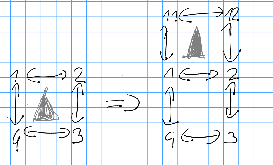
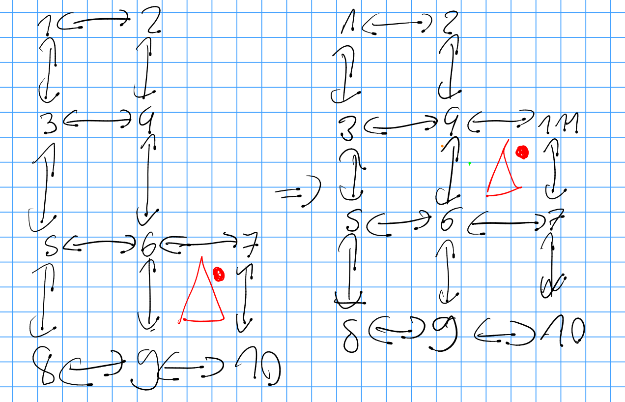
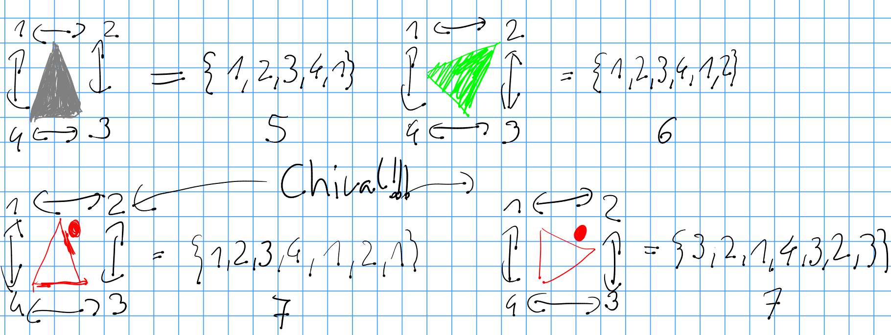
My represenations are not chiral, so i ran into problems with red, which could be solved by understanding that the problem was created by chirality.

enter image description here

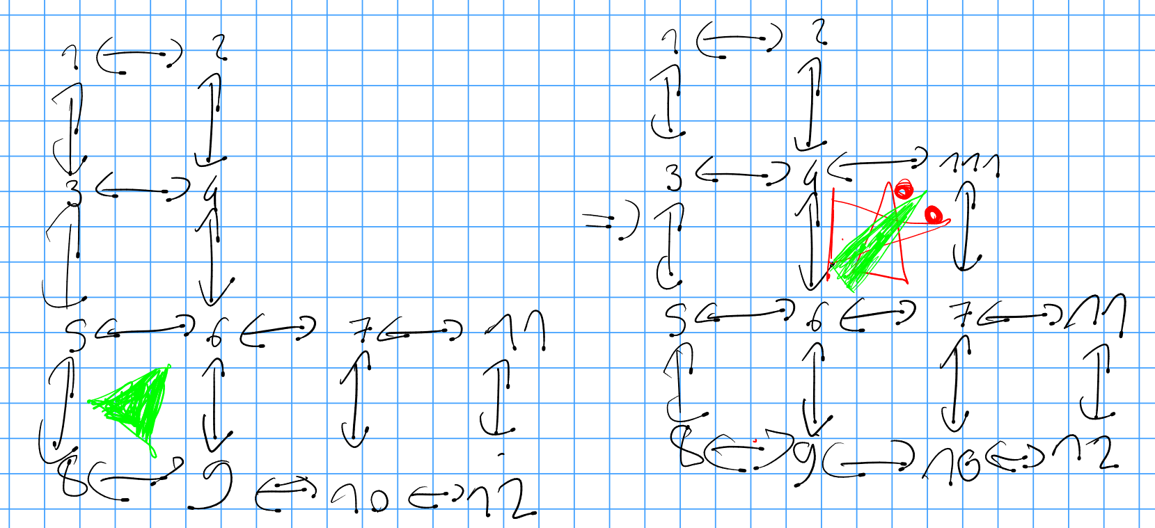
The dot always points away from the coordinate axis.

enter image description here

The code looks like that:

WolframModel[{
    {
     {5,6,9,8,5,6},
     {1,2},{2,1},{2,4},{4,2},{4,3},{3,4},{3,1},{1,3},
     {4,6},{6,4},{6,5},{5,6},{5,3},{3,5},
     {6,9},{9,6},{9,8},{8,9},{8,5},{5,8},
     {6,7},{7,6},{7,10},{10,7},{10,9},{9,10},
     {7,11},{11,7},{11,12},{12,11},{12,10},{10,12}
    } -> {
     {4,111,7,6,4,111,4},
     {7,111,4,6,7,111,7},
     {4,111,7,6,4,111},
     {1,2},{2,1},{2,4},{4,2},{4,3},{3,4},{3,1},{1,3},
     {4,6},{6,4},{6,5},{5,6},{5,3},{3,5},
     {6,9},{9,6},{9,8},{8,9},{8,5},{5,8},
     {6,7},{7,6},{7,10},{10,7},{10,9},{9,10},
     {7,11},{11,7},{11,12},{12,11},{12,10},{10,12},
     {4,111},{111,4},{111,7},{7,111}
    },
    {
     {6,7,10,9,6,7,6},
     {1,2},{2,1},{2,4},{4,2},{4,3},{3,4},{3,1},{1,3},
     {4,6},{6,4},{6,5},{5,6},{5,3},{3,5},
     {6,9},{9,6},{9,8},{8,9},{8,5},{5,8},
     {6,7},{7,6},{7,10},{10,7},{10,9},{9,10}
    } -> {
     {4,111,7,6,4,111,4},
     {1,2},{2,1},{2,4},{4,2},{4,3},{3,4},{3,1},{1,3},
     {4,6},{6,4},{6,5},{5,6},{5,3},{3,5},
     {6,9},{9,6},{9,8},{8,9},{8,5},{5,8},
     {6,7},{7,6},{7,10},{10,7},{10,9},{9,10},
     {4,111},{111,4},{111,7},{7,111}
    },
    {{1,2,3,4,1},{1,2},{2,1},{2,3},{3,2},{3,4},{4,3}}->
        {{11,12,2,1,11},{1,2},{2,1},{2,3},{3,2},{3,4},{4,3},{11,1},{1,11},{11,12},{12,11},{12,2},{2,12}}
},{
    {1,2,3,4,1},{2,3,4,1,2},{3,4,1,2,3},{4,1,2,3,4},
    {1,2,3,4,1,2},{2,3,4,1,2,3},{3,4,1,2,3,4},{4,1,2,3,4,1},
    {1,2},{2,1},{2,3},{3,2},{3,4},{4,3},{4,1},{1,4}
}
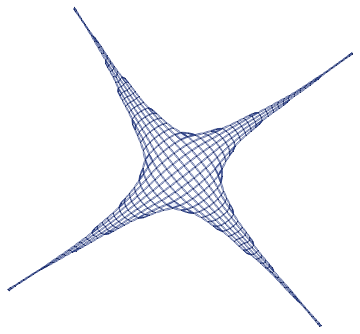
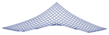
, 32, "FinalStatePlot"]

Thank You, Malthe Andersen,

after solving this toy problem, we can strive to attack bigger problems. The solution has more potential for optimization to run faster but now we can finaly say that we can build a 2d grid.

Thank you for the interesting post. I rendered a video of your solution in 3d:

2d grid model example video

Just to examine the layout and the causality of the model.

Thank you again. Tuomas

POSTED BY: Tuomas Sorakivi
Reply to this discussion
Community posts can be styled and formatted using the Markdown syntax.
Reply Preview
Attachments
Remove
or Discard

Group Abstract Group Abstract