MODERATOR NOTE: a submission to computations art contest, see more: https://wolfr.am/CompArt-22
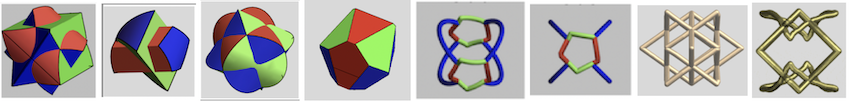
All the above "objects" are derived from the intersection of (polygonal) cylinders. In my community contribution, "From Intersecting Cylinders to Ambiguous Rings", I demonstrated that with just 2 cylinders, a lot of interesting, "ambiguous" or "shape-shifting" objects can be created. It was therefor tempting to find out what could be done by intersecting 3 i.o. 2 polygonal cylinders. Here is what I came up with:
1. Polygonal Cylinders
Polygonal cylinders here are right prims with regular n-gons as bases. For the parametric representation of a polygonal based cylinder we need an expression for the radius of its cross section in function of the angle around its axis. Here is the compiled version of my Wolfram Function Repository resource function RegularPolygonAngleRadius:
polyRadiusCF =
  Compile[{{t, _Real}, {t0, _Real}, {r, _Real}, {n, _Integer}},
   r Cos[\[Pi]/n] Sec[Mod[t - t0, (2 \[Pi])/n] - \[Pi]/n],
   CompilationTarget -> "C"];
The above function polyRadiusCF[t, t0, r, n] computes the polar radius at angle (t-t0) with respect to the x axis of a regular polygon with n vertices and radius r (n=Infinity can be used for circular cross sections). The function can be used to create parametric plots of regular polygonal cylinders: The function polyCylinderCF[t, t0, r, n, ax, v] computes the parametric representation, with parameters t and v, of a polygonal cylinder centered at coordinate axis ax (1 for x-axis, 2 for y-axis or 3 for z-axis). The radius of the circumscribed circular cylinder is r, n is the number of vertices and the cylinder is rotated with angle t0 around its axis.
polyCylinderCF =
  Compile[{{t, _Real}, {t0, _Real}, {r, _Real}, {n, _Integer}, {axis, \
_Integer}, {v, _Real}},
   Insert[
    AngleVector[{r Cos[\[Pi]/n] Sec[(2 ArcTan[Cot[1/2 n (t - t0)]])/
        n], t}], v, axis], CompilationTarget -> "C"];
cols = {Red, Green, Blue, Yellow};
Show[MapThread[
  ParametricPlot3D[
    polyCylinderCF[t, 1.25, 1, #3, #1, v], {t, 0, 2 Pi}, {v, -3, 3},
    PlotStyle -> FaceForm[#2, Yellow], BoundaryStyle -> Thick] &, {{1,
     2, 3}, Most[cols], {4, 5, 3}}]]
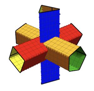
2. Intersection of 3 Polygonal Cylinders
A realistic presentation of the cylinders must include the holes cut into each cylinder at the intersection. This is achieved using RegionFunction. For each cylinder, its RegionFunction defines the incisions cut by the other two cylinders perpendicular to its axis. regioFn uses the following parameters: c1 is the coordinate of the cylinder's axis, c2 the coordinate of an intersecting cylinder's axis, n3, r3 and t03 are the number of vertices, radius and rotation of the third cylinder.
regioFn[c1_, c2_, t03_, r3_, n3_] :=
 c1^2 + c2^2 > polyRadiusCF[ArcTan[c1, c2], t03, r3, n3]^2
This example, of regioFn is for the hole cut by the y-axis cylinder in the x-axis cylinder:
regioFn[x, y, t0z, rz, nz]
The RegionFunction for each cylinder consists of two of these regioFn. One for each perpendicular cylinder and joined by the Boolean And. Here is the RegionFunction for the x-axis cylinder:
And[regioFn[x, y, t0z, rz, nz], regioFn[x, z, t0y, ry, ny]] &
Similarly, to define the boundaries of the cylinder incisions, a MeshFunctions is needed. This is simply the regioFn with the Boolean Greater replaced by the operator Subtract:
meshFn[c1_, c2_, t03_, r3_, n3_] :=
 Subtract[c1^2 + c2^2, polyRadiusCF[ArcTan[c1, c2], t03, r3, n3]^2]
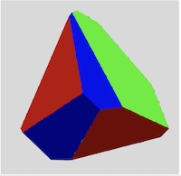
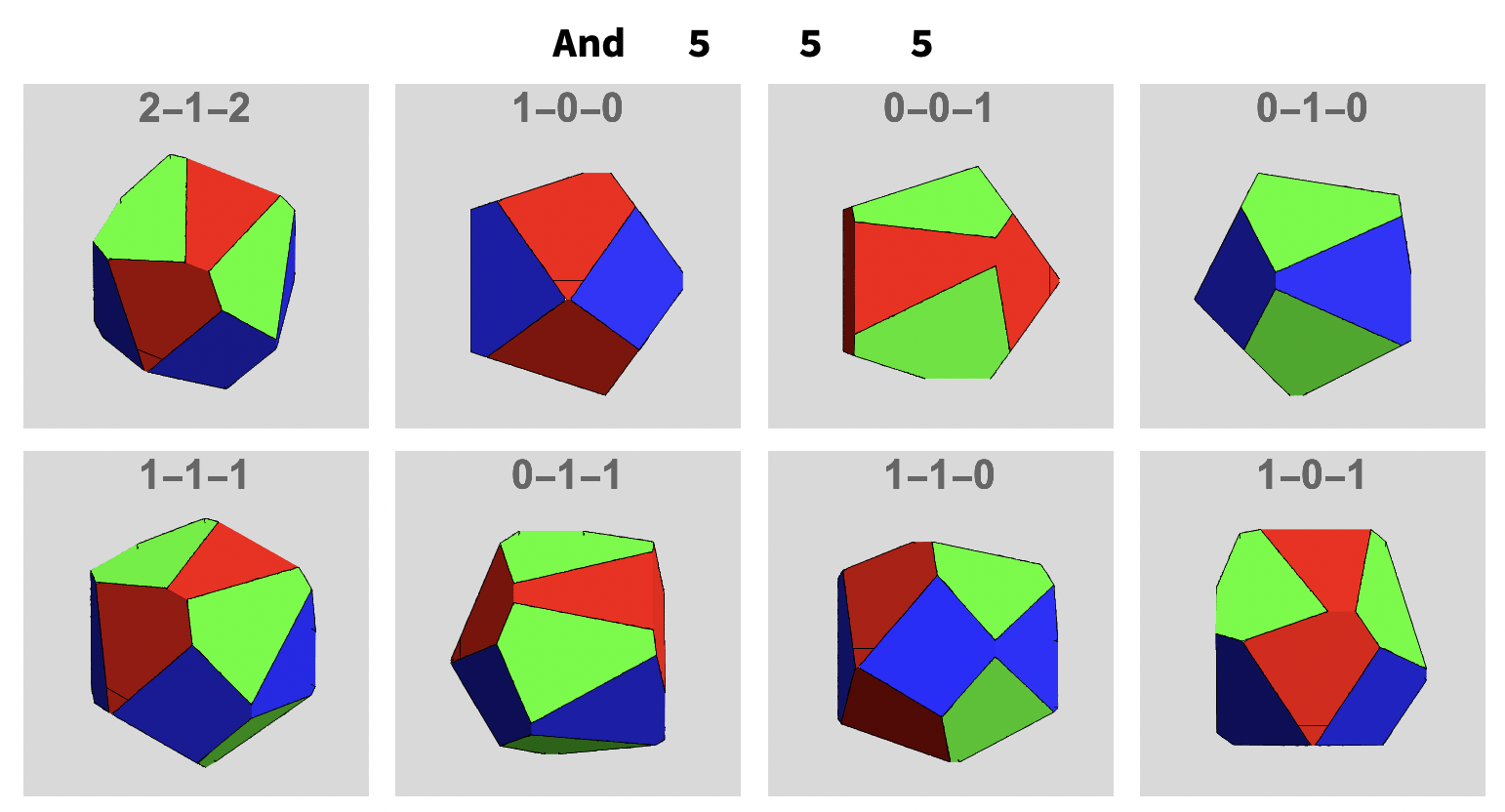
An example is the intersection of a pentagonal, square and triangular cylinder:
optCy = {MaxRecursion -> 5, Axes -> False, Boxed -> False,
   Mesh -> {{.0075}}, MeshStyle -> Directive[Thickness[.0075], Black]};
vwps = {{4, 2, 5}, {7, 0, 0}, {0, 0, 7}, {0, 7, 0}, {4, 4, 4}, {0, 5,
    5}, {5, 5, 0}, {5, 0, 5}};
lbls = {"2-1-2", "1-0-0", "0-0-1", "0-1-0", "1-1-1", "0-1-1", "1-1-0",
    "1-0-1"};
Module[{nx = 4, ny = 3, nz = 5, rx = 1.1, ry = .95, rz = 1, t0x = .25,
   t0y = 1.1, t0z = -1.2, pred = Greater},
 GraphicsGrid[
  Partition[
   MapThread[
    Show[
      {ParametricPlot3D[
        polyCylinderCF[t, t0x, rx, nx, 1, v], {t, 0, 2 Pi}, {v, -3, 3},
        PlotStyle -> {FaceForm[Green, LightYellow]}, Evaluate@optCy,
        RegionFunction -> (And[regioFn[#1, #3, t0y, ry, ny],
            regioFn[#1, #2, t0z, rz, nz]] &),
        MeshFunctions -> {meshFn[#1, #3, t0y, ry, ny] &,
          meshFn[#1, #2, t0z, rz, nz] &}],
       ParametricPlot3D[
        polyCylinderCF[t, t0y, ry, ny, 2, v], {t, 0, 2 Pi}, {v, -3, 3},
        PlotStyle -> {FaceForm[LightYellow, Red]}, Evaluate@optCy,
        RegionFunction -> (And[regioFn[#2, #3, t0x, rx, nx],
            regioFn[#1, #2, t0z, rz, nz]] &),
        MeshFunctions -> {meshFn[#2, #3, t0x, rx, nx] &,
          meshFn[#1, #2, t0z, rz, nz] &}],
       ParametricPlot3D[
        polyCylinderCF[t, t0z, rz, nz, 3, v], {t, 0, 2 Pi}, {v, -3, 3},
        PlotStyle -> {FaceForm[Lighter[Blue, .5], LightYellow]},
        Evaluate@optCy,
        RegionFunction -> (And[regioFn[#2, #3, t0x, rx, nx],
            regioFn[#1, #3, t0y, ry, ny]] &),
        MeshFunctions -> {meshFn[#2, #3, t0x, rx, nx] &,
          meshFn[#1, #3, t0y, ry, ny] &}]},
      ViewPoint -> #1, PlotRange -> 6,
      PlotLabel -> Style[#2, Bold, 12]] &, {vwps[[;; 4]],
     lbls[[;; 4]]}], 4]]]
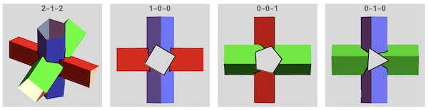
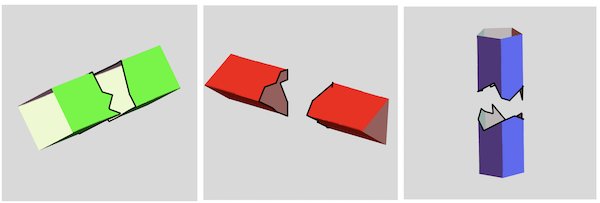
The labels at the top of the plots above are the view vectors. The plots below show the three cylinders separately with the incisions (holes) cut out by their 2 neighboring cylinders:
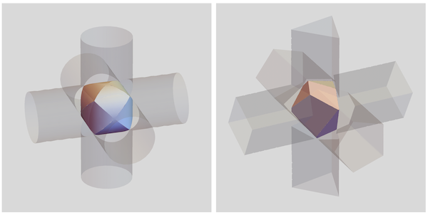
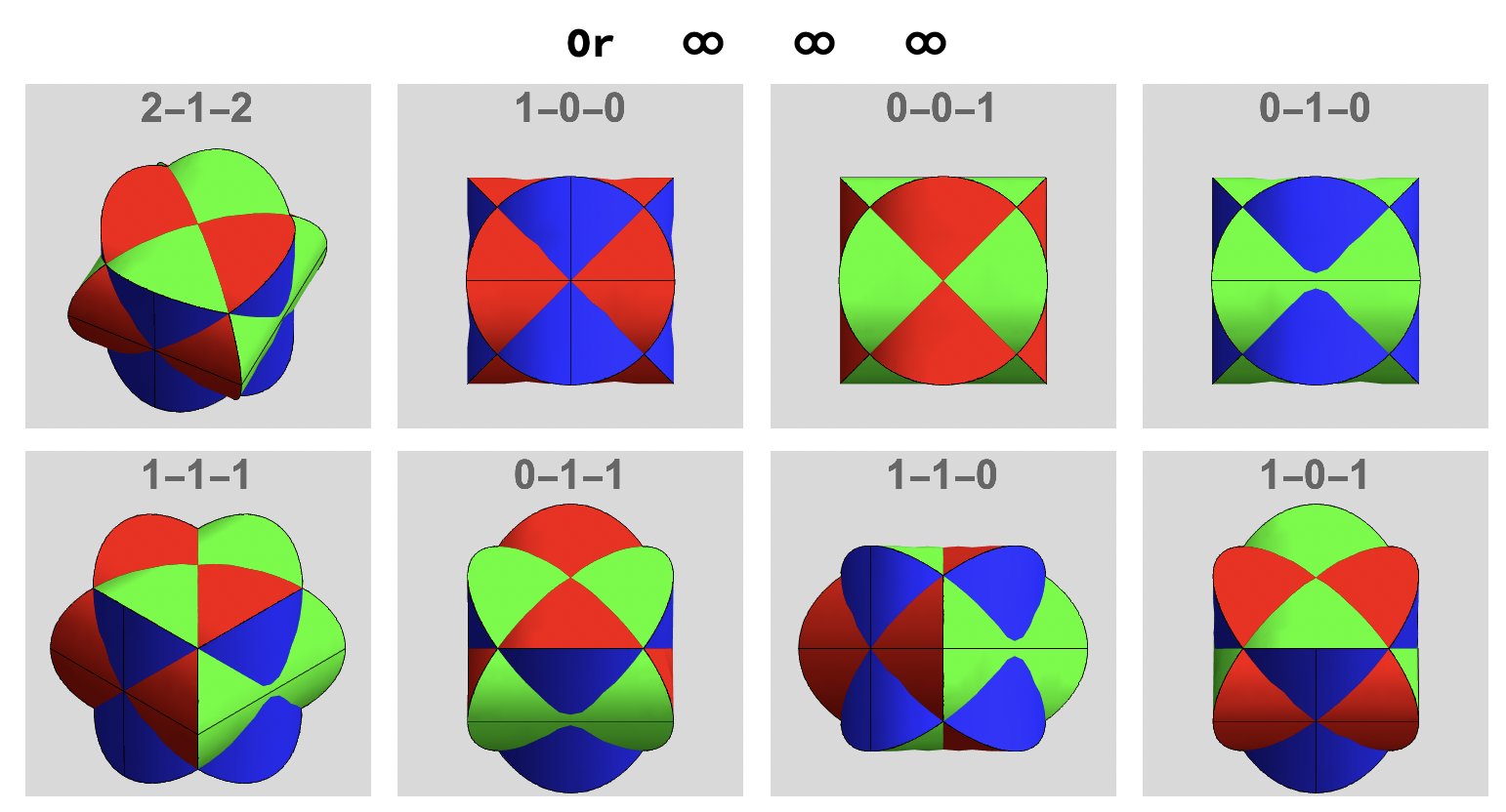
3. Steinmetz-type Solids (surfaces)
The union between two or three cylinders is known as a Steinmetz Solid. Below are two examples : the classical Steinmetz solid with 3 circular cylinders (L) and the polygonal version(R) with a 3 , 4- and 5-gonal based cylinder.
To obtain Steinmetz type "solids" i. o. cylinders, the RegionFunction regioFn has to be changed to regioFnSM by replacing the Boolean Greater with Less . This way, the cut-away parts of the cylinders are produced i.o. the cylinders and this results in a hollow Steinmetz-type surface.
regioFnSM[c1_, c2_, t03_, r3_, n3_] :=
 Less[c1^2 + c2^2, polyRadiusCF[ArcTan[c1, c2], t03, r3, n3]^2]
There is an infinite number of combinations of n, r and t0. The following code generates one of them.
Module[{nx, ny, nz, rx, ry, rz, t0x, t0y, t0z}, {nx, ny, nz} =
  RandomChoice[{3, 4, 5, 100}, 3];
 {rx, ry, rz} = RandomReal[{.25, 1}, 3];
 {t0x, t0y, t0z} = RandomReal[{-3.14, 3.14}, 3];
 optSM = {MaxRecursion -> 5, Axes -> False, Boxed -> False,
   Mesh -> None,
   BoundaryStyle -> Directive[Thickness[.05], Opacity[0]]};
 Show[
  {ParametricPlot3D[
    polyCylinderCF[t, t0x, rx, nx, 1, v], {t, 0, 2 Pi}, {v, -3, 3},
    PlotStyle -> Green, Evaluate@optSM,
    RegionFunction -> (And[regioFnSM[#1, #3, t0y, ry, ny],
        regioFnSM[#1, #2, t0z, rz, nz]] &),
    MeshFunctions -> {meshFn[#1, #3, t0y, ry, ny] &,
      meshFn[#1, #2, t0z, rz, nz] &}],
   ParametricPlot3D[
    polyCylinderCF[t, t0y, ry, ny, 2, v], {t, 0, 2 Pi}, {v, -3, 3},
    PlotStyle -> Red, Evaluate@optSM,
    RegionFunction -> (And[regioFnSM[#2, #3, t0x, rx, nx],
        regioFnSM[#1, #2, t0z, rz, nz]] &),
    MeshFunctions -> {meshFn[#2, #3, t0x, rx, nx] &,
      meshFn[#1, #2, t0z, rz, nz] &}],
   ParametricPlot3D[
    polyCylinderCF[t, t0z, rz, nz, 3, v], {t, 0, 2 Pi}, {v, -3, 3},
    PlotStyle -> Blue, Evaluate@optSM,
    RegionFunction -> (And[regioFnSM[#2, #3, t0x, rx, nx],
        regioFnSM[#1, #3, t0y, ry, ny]] &),
    MeshFunctions -> {meshFn[#2, #3, t0x, rx, nx] &,
      meshFn[#1, #3, t0y, ry, ny] &}]},
  PlotRange -> 1, Background -> LightGray]]
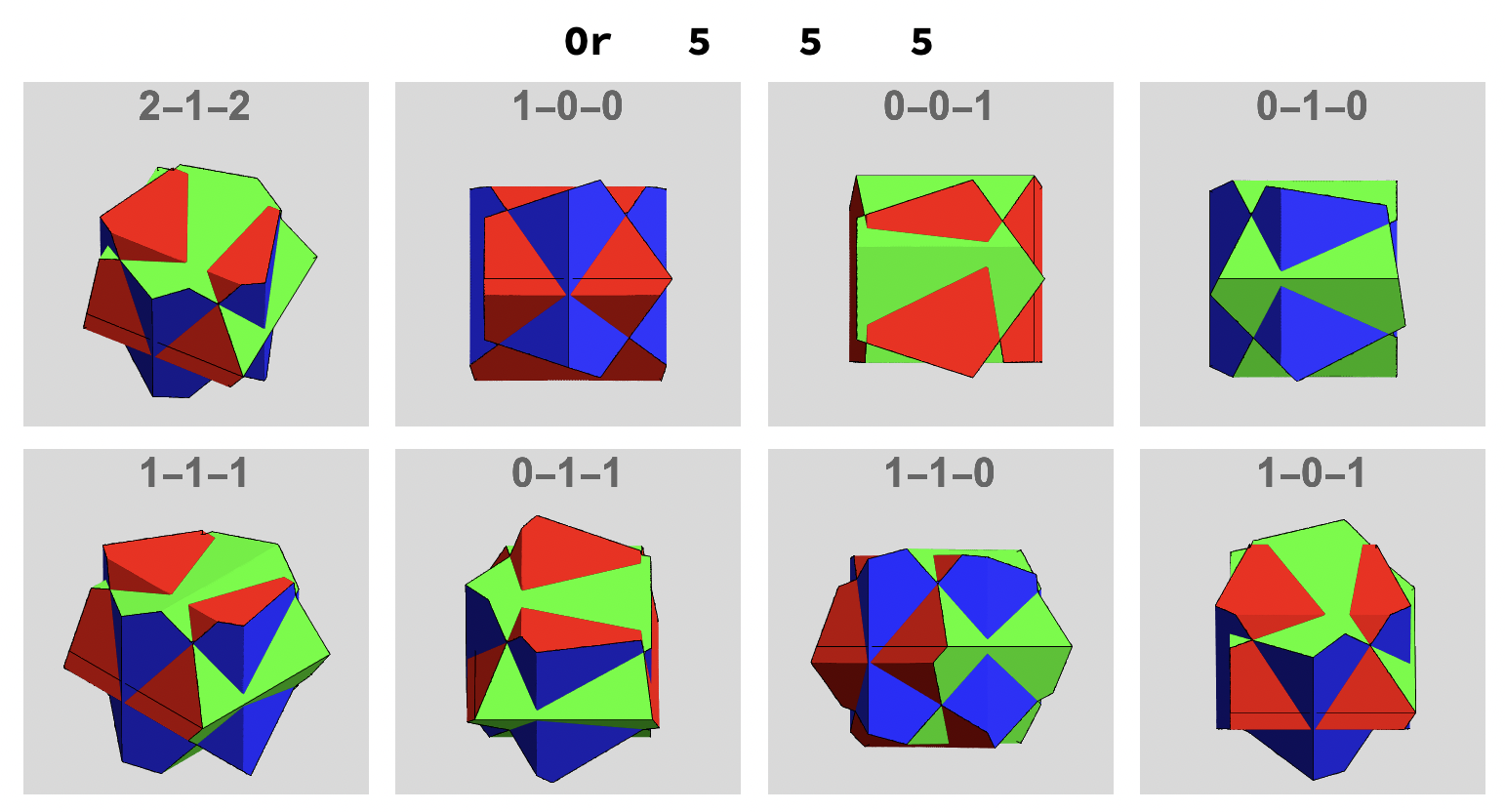
Here are 2 collections of Steinmetz type surfaces with different n-gonal bases and seen from different view directions.The operator And/Or and the number of vertices are indicated at the top and the view vector is indicated on each image.
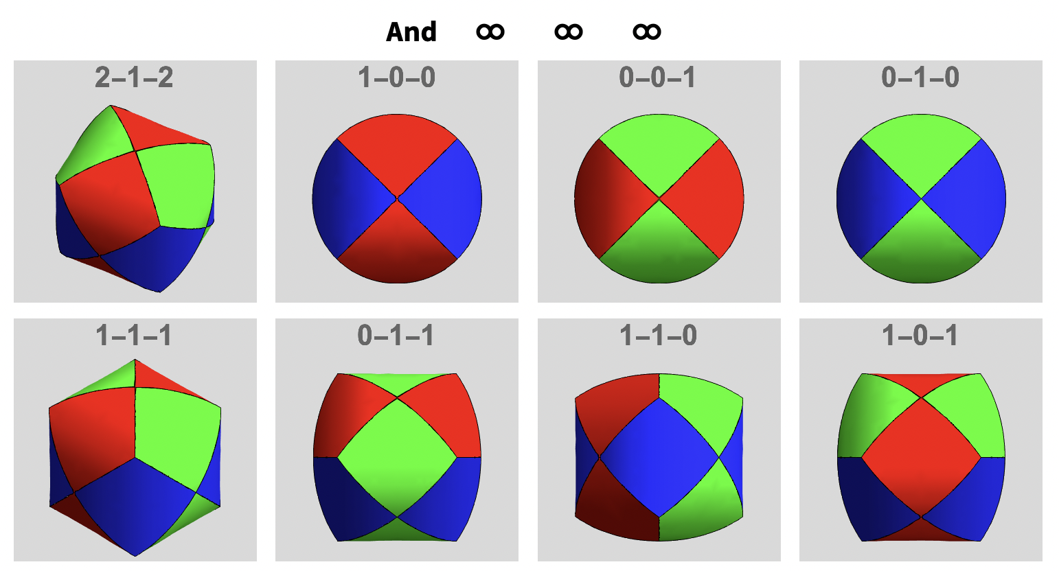
One can also change the And operator to Or and get a completely new range of surfaces with the same n, r, t0 parameter combinations:
RegionFunction -> (Or[regioFnSM[#1, #3, t0y, ry, ny],
    regioFnSM[#1, #2, t0z, rz, nz]] &)
The following produces the frames for the GIF animation of a rotating Steinmetz Surface created by intersecting 3 pentagonal based cylinders:
frames =
  Module[{nx = 5, ny = 5, nz = 5, rx = 1.05, ry = .85, rz = .9,
    t0x = 0, t0y = -1.1, t0z = .85, pred = Or},
   ParallelTable[
    Show[{ParametricPlot3D[
       polyCylinderCF[t, t0x, rx, nx, 1, v], {t, 0, 2 \[Pi]}, {v, -3,
        3}, PlotStyle -> Green, Evaluate[optSM],
       RegionFunction -> (pred[regioFnSM[#1, #3, t0y, ry, ny],
           regioFnSM[#1, #2, t0z, rz, nz]] &),
       MeshFunctions -> {meshFn[#1, #3, t0y, ry, ny] &,
         meshFn[#1, #2, t0z, rz, nz] &}],
      ParametricPlot3D[
       polyCylinderCF[t, t0y, ry, ny, 2, v], {t, 0, 2 \[Pi]}, {v, -3,
        3}, PlotStyle -> Red, Evaluate[optSM],
       RegionFunction -> (pred[regioFnSM[#2, #3, t0x, rx, nx],
           regioFnSM[#1, #2, t0z, rz, nz]] &),
       MeshFunctions -> {meshFn[#2, #3, t0x, rx, nx] &,
         meshFn[#1, #2, t0z, rz, nz] &}],
      ParametricPlot3D[
       polyCylinderCF[t, t0z, rz, nz, 3, v], {t, 0, 2 \[Pi]}, {v, -3,
        3}, PlotStyle -> Blue, Evaluate[optSM],
       RegionFunction -> (pred[regioFnSM[#2, #3, t0x, rx, nx],
           regioFnSM[#1, #3, t0y, ry, ny]] &),
       MeshFunctions -> {meshFn[#2, #3, t0x, rx, nx] &,
         meshFn[#1, #3, t0y, ry, ny] &}]},
     ViewPoint -> {Cos[\[Phi]], Sin[\[Phi]], 0}], {\[Phi], -3.14,
     3.14, 1}]];
Export[NotebookDirectory[] <> "file", frames,
 AnimationRepetitions -> Infinity]
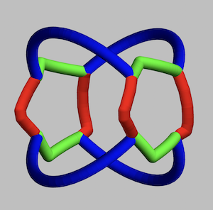
4. "Shape-shifting" or "ambiguous" rings
The boundaries of the intersections themselves can be considered as rings. "view-dependent" rings since their apparent shape will shift continuously as it is viewed from different directions. To obtain the rings, we need to eliminate the cylinders by setting the Opacity to 0 and defining MeshFunctions for a Mesh very close to the intersection e.g. Mesh->{{0.01}}:
Module[{rx, ry, rz, nx, ny, nz, t0x, t0y, t0z, curveX, curveY, curveZ,
   tubeRule}, {nx, ny, nz} = {100, 5, 100}; {rx, ry, rz} = {1., 1,
   1}; {t0x, t0y, t0z} = {.25, 1.1, -1.2};
 tubeRule = Line[pts_] :> Tube[Line[pts], .1];
 curveX =
  ParametricPlot3D[
   polyCylinderCF[t, t0x, rx, nx, 1, v], {t, 0, 2 \[Pi]}, {v, -2, 2},
   Axes -> False, Boxed -> False, PlotStyle -> Opacity[0],
   RegionFunction -> (regioFn[#1, #3, t0y, ry, ny] &&
       regioFn[#1, #2, t0z, rz, nz] &), Mesh -> {{0.01}},
   MeshFunctions -> {meshFn[#1, #3, t0y, ry, ny] &}];
 curveY =
  ParametricPlot3D[
   polyCylinderCF[t, t0y, ry, ny, 2, v], {t, 0, 2 \[Pi]}, {v, -2, 2},
   Axes -> False, Boxed -> False, PlotStyle -> Opacity[0],
   RegionFunction -> (regioFn[#2, #3, t0x, rx, nx] &&
       regioFn[#1, #2, t0z, rz, nz] &), Mesh -> {{0.01}},
   MeshFunctions -> {meshFn[#1, #2, t0z, rz, nz] &}];
 curveZ =
  ParametricPlot3D[
   polyCylinderCF[t, t0z, rz, nz, 3, v], {t, 0, 2 \[Pi]}, {v, -2, 2},
   Axes -> False, Boxed -> False, PlotStyle -> Opacity[0],
   RegionFunction -> (regioFn[#2, #3, t0x, rx, nx] &&
       regioFn[#1, #3, t0y, ry, ny] &), Mesh -> {{0.01}},
   MeshFunctions -> {meshFn[#3, #2, t0x, rx, nx] &}];
 Graphics3D[({AbsoluteThickness[5], #1[[1]]} &) /@ {curveX, curveY,
    curveZ}, PlotRange -> 1, Boxed -> False]]
Here is an example of a ring produced by the intersection of two circular and one pentagonal cylinders:
Even by adapting the parameters of 3 circular cylinders, we get some interesting ring objects with surprisingly different "view-dependent" appearances.
GIFs can demonstrate more clearly the "shape shifting". Here of a ring cut by intersecting two square and one circular based cylinders.
Or by using the new MaterialShading directives:
5. Shape-Shifting by rotating individual cylinders
Shape shifting cannot only be observed by rotating the intersections proper but also by rotating the cylinders that intersect as the rings. The following code rotates the z-axis cylinder in a square/square/circular based cylinder intersection:
Shape shifting cannot only be observed by rotating the intersections proper but also by rotating the cylinders that intersect as the rings. The following code rotates the z-axis cylinder in a square/square/circular based cylinder intersection:
With[{nx = 4, ny = 100, nz = 4, rx = 1., ry = 1, rz = 1, t0x = 0,
   t0y = 0},
  frames =
   ParallelTable[
    Show[{ParametricPlot3D[
        polyCylinderCF[t, t0x, rx, nx, 1, v], {t, 0, 2 \[Pi]}, {v, -3,
          3}, Axes -> False, Boxed -> False, PlotStyle -> Opacity[0],
        RegionFunction -> (regioFn[#1, #3, t0y, ry, ny] &&
            regioFn[#1, #2, t0z, rz, nz] &), Mesh -> {{0.01}},
        MeshFunctions -> {meshFn[#1, #3, t0y, ry, ny] &},
        MeshStyle -> MaterialShading["Brass"]] /.
       Line[pts_] -> Tube[Line[pts], .075],
      ParametricPlot3D[
        polyCylinderCF[t, t0y, ry, ny, 2, v], {t, 0, 2 \[Pi]}, {v, -3,
          3}, Axes -> False, Boxed -> False, PlotStyle -> Opacity[0],
        RegionFunction -> (regioFn[#2, #3, t0x, rx, nx] &&
            regioFn[#1, #2, t0z, rz, nz] &), Mesh -> {{0.01}},
        MeshFunctions -> {meshFn[#1, #2, t0z, rz, nz] &},
        MeshStyle -> MaterialShading["Brass"]] /.
       Line[pts_] -> Tube[Line[pts], .075],
      ParametricPlot3D[
        polyCylinderCF[t, t0z, rz, nz, 3, v], {t, 0, 2 \[Pi]}, {v, -3,
          3}, Axes -> False, Boxed -> False, PlotStyle -> Opacity[0],
        RegionFunction -> (regioFn[#2, #3, t0x, rx, nx] &&
            regioFn[#1, #3, t0y, ry, ny] &), Mesh -> {{0.01}},
        MeshFunctions -> {meshFn[#3, #2, t0x, rx, nx] &},
        MeshStyle -> MaterialShading["Brass"]] /.
       Line[pts_] -> Tube[Line[pts], .075]}, SphericalRegion -> True,
     PlotRange -> 2, Background -> LightGray, ImageSize -> 200,
     ViewPoint -> {0, 10, 0}, ViewAngle -> 3.6 \[Degree],
     Boxed -> False, Axes -> False, Lighting -> "ThreePoint"], {t0z,
     0, 3.14, .05}]];
This is the same code applied to the intersection ring of 3 square cylinders forming this copper ring:
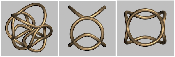
To conclude: a complete collection of rings resulting from intersecting random polygonal based cylinder combinations. The first column is a default view and the last3 columns are views along the 3 coordinate axes of the same ring.
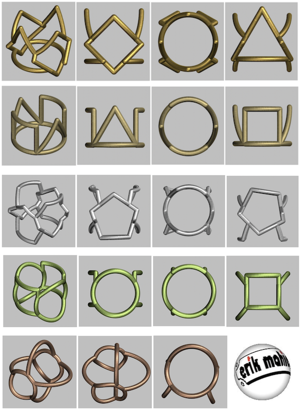
Maybe an idea for the creation of some beautiful 3D printed Wolfram jewelry Christmas gifts?!


