I am sharing a program for creating circuit diagrams. The share location is: http://cit.blinn.edu/Physics/Mathematica/
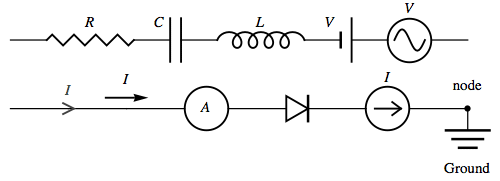
Circuit components examples are shown below.

The basic syntax is:
Graphics[
 DrawCircuit[<|"a" -> {0, 0}, "b" -> {1, 0}|>,
  {{{"a", "b"}, {Inductor["L"], Capacitor["C"]}}}, {{"a",
    Node["a", TextOffset -> .75]}, {"b",
    Node["b", TextOffset -> .75]}}, TextOffsetScale -> .75],
 BaseStyle -> {12, Italic, FontFamily -> "Times"}]
with the output.

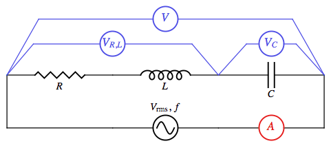
Here is a more complex example with code.
With[{a = .5, colV = RGBColor[.3, .3, .9],
  colA = RGBColor[.9, .1, .1]},
 Graphics[{DrawCircuit[
    {{0, -a}, {3, -a}, {0, 0}, {1, 0}, {2, 0}, {3,
      0}, {1, -a}, {2, -a}},
    {
     {{7,
       8}, {ACVoltage["\!\(\*SubscriptBox[\(V\), \(rms\)]\), \!\(\*
StyleBox[\"f\",\nFontSlant->\"Italic\"]\)",
        TextOffset -> 1.25]}}, {{1, 7}, {}}, {{2,
       8}, {InlineMeter[Style["A", 14, Italic, colA],
        InlineMeterDirectives -> colA]}},
     {{1, 3}, {}}, {{2, 6}, {}},
     {{3, 4}, {Resistor[Style["R", Italic], TextOffset -> -1]}},
     {{4, 5}, {Inductor[Style["L", Italic], TextOffset -> -1]}},
     {{5,
       6}, {Capacitor[Style["C", Italic],
        TextOffset -> {0, -1.625}]}}, {OffsetPoints[{3,
        5}, .125, .625,
       WireDirectives -> colV], {InlineMeter[
        Style["\!\(\*SubscriptBox[\(V\), \(R, L\)]\)", 14, colV],
        InlineMeterDirectives -> colV]}},
     {OffsetPoints[{5, 6}, .265, .625,
       WireDirectives -> colV], {InlineMeter[
        Style["\!\(\*SubscriptBox[\(V\), \(C\)]\)", 14, colV],
        InlineMeterDirectives -> colV]}},
     {OffsetPoints[{3, 6}, .1, 1.125,
       WireDirectives -> colV], {InlineMeter[
        Style["V", 14, Italic, colV],
        InlineMeterDirectives -> colV]}}
     }
    ]
   }, BaseStyle -> {12, FontFamily -> "Times"}]]
