This post is to show how to create and generate Unified Modeling Language (UML) diagrams in Mathematica. It is related to programming in Mathematica using Object-Oriented Design Patterns.
Package functions
This command imports the package UMLDiagramGeneration.m :
Import["https://raw.githubusercontent.com/antononcube/MathematicaForPrediction/master/Misc/UMLDiagramGeneration.m"]
The package provides the functions UMLClassNode and UMLClassGraph.
The function UMLClassNode has the signature
UMLClassNode[classSymbol, opts]
UMLClassNode creates a Grid object with a class name and its methods for the specified class symbol. The option "Abstact" can be used to specify abstract class names and methods. The option "EntityColumn" can be used to turn on and off the explanations column.
The function UMLClassGraph that has the signature:
UMLClassGraph[symbols, abstractMethodsPerSymbol, symbolAssociations, symbolAggregations, opts]
UMLClassGraph creates an UML graph diagram for the specified symbols (representing classes) and their relationships. It takes as options the options of UMLClassNode and Graph.
UML diagrams creation
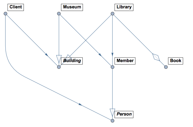
Let us visualize a simple relationship between buildings, people, books, and a client program.
UMLClassGraph[{Library \[DirectedEdge] Building,
  Museum \[DirectedEdge] Building,
  Member \[DirectedEdge] Person}, {}, {Library <-> Member,
  Museum \[DirectedEdge] Member, Client \[DirectedEdge] Building,
  Client \[DirectedEdge] Person}, {Library \[DirectedEdge] Book},
 "Abstract" -> {Building, Person},
 "EntityColumn" -> False, VertexLabelStyle -> "Text",
 ImageSize -> Large, GraphLayout -> "LayeredDigraphEmbedding"]

In the diagram above the classes Person and Building are abstract (that is why are in italic). Member inherits Person, Library and Museum inherit Building. Library can contain (many) Book objects and it is associated with Member. Client associates with Building and Person.
UML diagram generation
The main package function UMLClassGraph is capable of generating UML diagrams over Design Patterns code written in the style exemplified and described in my WTC 2015 talk Object-Oriented Design Patterns.
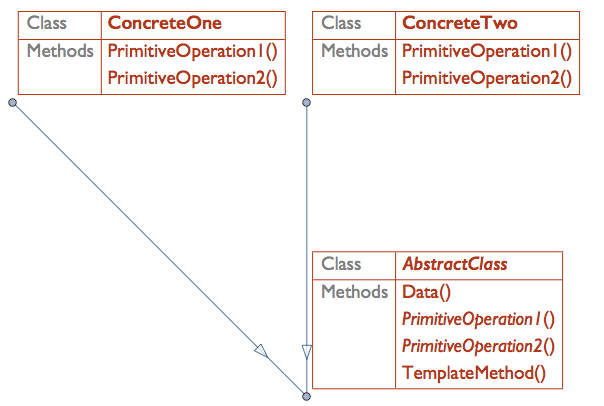
Let us look into a simple UML generation example for the design pattern Template Method.
Here is the Mathematica code for that design pattern:
Clear[AbstractClass, ConcreteOne, ConcreteTwo];

CLASSHEAD = AbstractClass;
AbstractClass[d_]["Data"[]] := d;
AbstractClass[d_]["PrimitiveOperation1"[]] := d[[1]];
AbstractClass[d_]["PrimitiveOperation2"[]] := d[[2]];
AbstractClass[d_]["TemplateMethod"[]] :=
CLASSHEAD[d]["PrimitiveOperation1"[]] + CLASSHEAD[d]["PrimitiveOperation2"[]]

ConcreteOne[d_][s_] := Block[{CLASSHEAD = ConcreteOne}, AbstractClass[d][s]]
ConcreteOne[d_]["PrimitiveOperation1"[]] := d[[1]];
ConcreteOne[d_]["PrimitiveOperation2"[]] := d[[1]]*d[[2]];

ConcreteTwo[d_][s_] := Block[{CLASSHEAD = ConcreteTwo}, AbstractClass[d][s]]
ConcreteTwo[d_]["PrimitiveOperation1"[]] := d[[1]];
ConcreteTwo[d_]["PrimitiveOperation2"[]] := d[[3]]^d[[2]];
This command generates an UML diagram over the code above:
UMLClassGraph[{AbstractClass, ConcreteOne,
  ConcreteTwo}, {AbstractClass -> {"PrimitiveOperation1",
    "PrimitiveOperation2"}}, "Abstract" -> {AbstractClass},
 VertexLabelStyle -> "Subsubsection"]

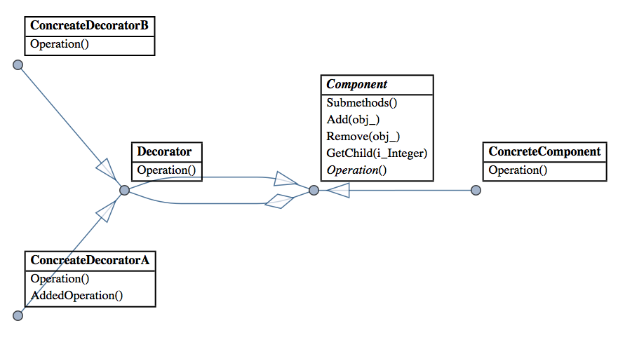
Here is a diagram generated over a Mathematica implementation of Decorator:

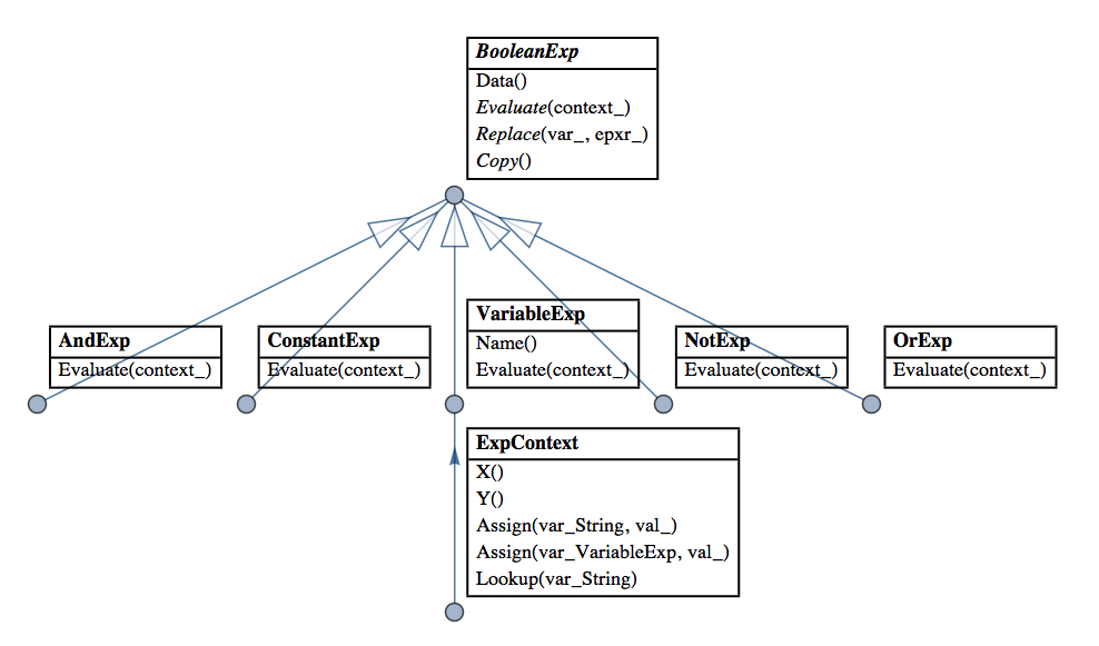
And here is a diagram for a concrete implementation of Interpreter for Boolean expressions:

(Interpreter is my favorite Design Pattern and I have made several Mathematica implementations that facilitate and extend its application. See these blog posts of mine: "Functional parsers" category in MathematicaForPrediction at WordPress).